
Inducing and driving integrated type dam fish passing device and using method thereof

An integrated, dam technology, applied in water conservancy engineering, marine engineering, climate change adaptation and other directions, can solve the problems of unsatisfactory fish passing effect, large area, high construction cost and operation and maintenance cost, etc. , The effect of low operating cost and high water utilization rate

Active Publication Date: 2018-12-14
HOHAI UNIV
View PDF4 Cites 3 Cited by
  • Summary
  • Abstract
  • Description
  • Claims
  • Application Information

AI Technical Summary

Problems solved by technology

At present, artificial fishways are generally used in engineering. Although some parameters such as water flow velocity and flow rate cater to some migratory fish, the scale of the project is often large, the cost of construction and operation and maintenance are high, and the effect of fish passing is difficult to achieve the ideal state.
The traditional dam fish passage system usually adopts an artesian artificial fishway, which not only has a complex structure, but also occupies a large area, and the project cost is high, and its limitations are relatively large
Especially for dams with a water level difference of more than 50 meters between upstream and downstream, the traditional artesian fishway is almost difficult to realize. Even if it is barely realized, the construction scale and engineering investment are quite considerable. The more fatal flaw is that the fish passing effect is often unsatisfactory

Method used


Image

  • Inducing and driving integrated type dam fish passing device and using method thereof
  • Inducing and driving integrated type dam fish passing device and using method thereof

Examples


Embodiment 1

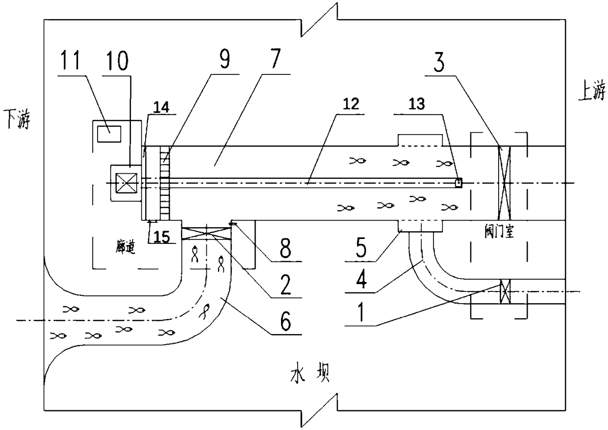
[0025] An induction driving integrated dam fish passing device, refer to figure 1, the device includes valve a1, valve b2, valve c3, water supply pipeline 4, decompression ring pipe 5, induction pipeline 6, comprehensive pipeline 7, screw rod 12, screw rod support 13, driving disc 9, end plate 14. Screw driving device 10, one end of the comprehensive pipeline 7 is set at the upstream of the dam, and the other end is set at the downstream of the dam, the water supply pipeline 4 is set at the upstream of the dam, and the induction pipeline 6 is set at the downstream of the dam. The valve a1 is set at the water inlet of the water supply pipeline 4, the decompression ring pipe 5 is sleeved on the outside of the upstream of the integrated pipeline 7, and both ends of the decompression ring pipe 5 are sealed, and the outer side of the integrated pipeline 7 is sleeved. The pipe wall of the decompression ring pipe 5 is provided with four rows of decompression through holes, and the wa...

Embodiment 2

[0028] An induction driving integrated dam fish passing device, refer to figure 1 , the device includes valve a1, valve b2, valve c3, water supply pipeline 4, decompression ring pipe 5, induction pipeline 6, comprehensive pipeline 7, screw rod 12, screw rod support 13, driving disc 9, end plate 14. Screw driving device 10, one end of the comprehensive pipeline 7 is set at the upstream of the dam, and the other end is set at the downstream of the dam, the water supply pipeline 4 is set at the upstream of the dam, and the induction pipeline 6 is set at the downstream of the dam. The valve a1 is arranged at the water inlet of the water supply pipeline 4, the decompression ring pipe 5 is sleeved on the outside of the upstream of the comprehensive pipeline 7, and both ends of the decompression ring pipe 5 are sealed, and the outside of the comprehensive pipeline 7 Four rows of decompression through holes are set on the pipe wall of the decompression ring pipe 5. The water outlet of...

Embodiment 3

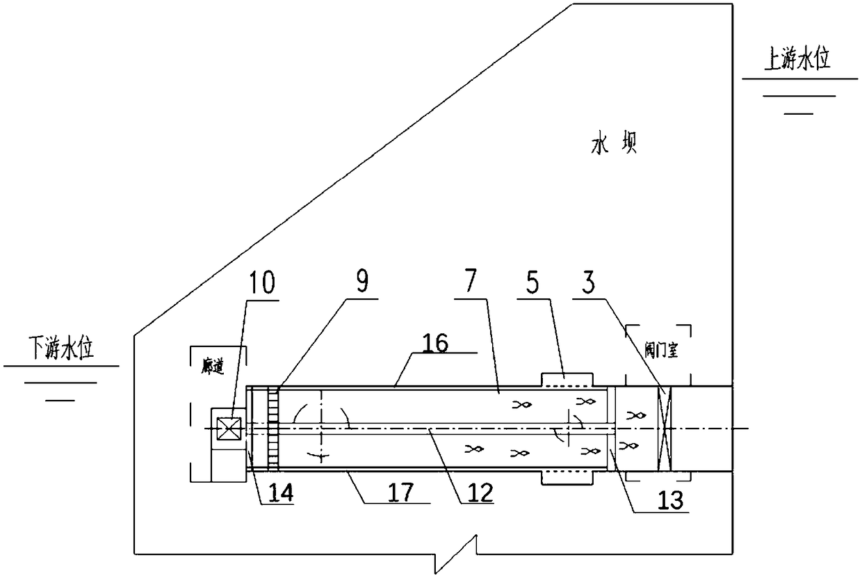
[0031] How to adopt the induction and drive integrated dam fish passing system device of the present invention as an example now, refer to figure 1 and figure 2 .

[0032] The device is arranged inside the dam structure, wherein a corridor is set on the downstream side of the dam, and a valve chamber is set on the upstream side of the dam, and the device includes a valve a 1, a valve b 2, a valve c 3, a water supply pipeline 4, a pressure reducing Ring pipe 5, induction pipeline 6, comprehensive pipeline 7, ultrasonic fish counting device 8, screw rod 12, screw rod support 13, driving plate 9, end plate 14, manhole 15, driving plate upper guide rail 16, driving plate lower guide rail 17 , screw driving device 10 and integrated control device 11. The valve a 1 and valve c 3 are electric valves, and both are equipped with fully closed and fully open position feedback switches. The valve chamber on the upstream side of the dam can facilitate the installation, inspection and ma...


PUM


Abstract

The invention discloses an inducing and driving integrated type dam fish passing device and a using method thereof, and belong to the field of water conservancy and hydropower engineering and ecological environmental protection engineering. The device comprises a valve a, a valve b, a valve c, a water supply pipeline, a pressure reduction annular pipe, an induction pipeline, a comprehensive pipeline, a screw, a screw support, a driving disc, an end plate and a screw driving device, one end of the comprehensive pipeline is arranged on the upstream of a dam, the other end of the comprehensive pipeline is arranged at the downstream of the dam, the water supply pipeline is arranged on the upstream of the dam, and the induction pipeline is arranged on the downstream of the dam. According to thedevice and the method, by utilizing the habit of the fish school for counter-current migration and combining the actual engineering characteristics of water retaining buildings such as the dam, the pressure water flow in the upstream of the dam is subjected to self-flowing pressure reduction and then flows into the downstream river channel of the dam through the pressure reduction annular pipe, and the fish school for counter-current migration in the downstream is induced and driven to the upstream through the screw driving device; and the remarkable advantages that the occupied area is small, the investment is saved, the effect is fast, the efficiency is high, the water utilization rate is high, installation, operation, maintenance and overhauling are convenient and the like are achieved.

Description

technical field [0001] The invention relates to the fields of water conservancy and hydropower engineering and ecological environmental protection engineering, in particular to an induction driving integrated dam fish passing device and a use method thereof. Background technique [0002] Due to the needs of various projects such as power generation, irrigation, landscape, and water conservancy, people often build water-retaining structures such as dams in rivers and other water systems. These water-retaining structures often hinder or block the migration of migratory fish and other aquatic organisms in the river. Cause direct or indirect damage or even destruction to aquatic organisms in the original river and other water systems. With the continuous improvement of my country's water energy and water resources development, more and more various barrages and other water-retaining structures will be built on the main stream and tributaries of the river. Although people have...

Claims


Application Information

Patent Timeline
Patent Type & Authority Applications(China)
IPC IPC(8): E02B8/08
CPCE02B8/08Y02A40/60
Inventor 吴浩伟傅宗甫
Owner HOHAI UNIV
Learn More