An induction and repelling integrated dam fish passing device and its application method
An integrated and dam technology, applied in water conservancy projects, sea area engineering, construction, etc., can solve the problems of unsatisfactory fish passing effect, high cost and operation and maintenance costs, and large floor area, and achieve no harm to fish passing efficiency and water volume High utilization rate and low operating cost
- Summary
- Abstract
- Description
- Claims
- Application Information
AI Technical Summary
Problems solved by technology
Method used
Image
Examples
Embodiment 1
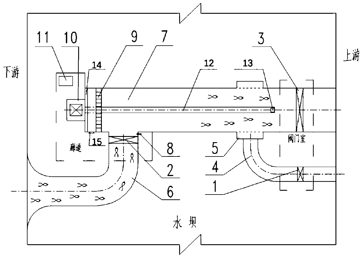
[0025] An induction driving integrated dam fish passing device, refer to figure 1, the device includes valve a 1, valve b 2, valve c 3, water supply pipeline 4, decompression ring pipe 5, induction pipeline 6, comprehensive pipeline 7, screw 12, screw support 13, driving disc 9, terminal Plate 14, screw driving device 10, one end of the comprehensive pipeline 7 is located upstream of the dam, the other end is located downstream of the dam, the water supply pipeline 4 is located upstream of the dam, and the induction pipeline 6 is located downstream of the dam, so The valve a1 is located at the water inlet of the water supply pipeline 4, the decompression ring pipe 5 is sleeved on the outside of the upstream of the comprehensive pipeline 7, and the two ends of the decompression ring pipe 5 are sealed, and the outside of the comprehensive pipeline 7 Four rows of decompression through holes are set on the pipe wall of the decompression ring pipe 5. The water outlet of the water s...
Embodiment 2
[0028] An induction driving integrated dam fish passing device, refer to figure 1 , the device includes valve a 1, valve b 2, valve c 3, water supply pipeline 4, decompression ring pipe 5, induction pipeline 6, comprehensive pipeline 7, screw 12, screw support 13, driving disc 9, terminal Plate 14, screw driving device 10, one end of the comprehensive pipeline 7 is located upstream of the dam, the other end is located downstream of the dam, the water supply pipeline 4 is located upstream of the dam, and the induction pipeline 6 is located downstream of the dam, so The valve a1 is arranged at the water inlet of the water supply pipeline 4, the decompression ring pipe 5 is sleeved on the outside of the upstream of the integrated pipeline 7, and both ends of the decompression ring pipe 5 are sealed, and the integrated pipeline 7 Four rows of decompression through-holes are provided on the pipe wall of the decompression ring pipe 5 sleeved on the outside. The water outlet of the w...
Embodiment 3
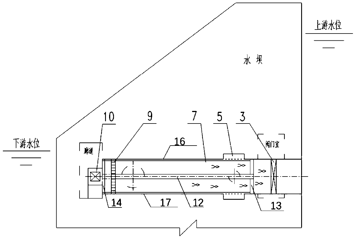
[0031] How to adopt the induction and drive integrated dam fish passing system device of the present invention as an example now, refer to figure 1 and figure 2 .
[0032] The device is arranged inside the dam structure, wherein a corridor is set on the downstream side of the dam, and a valve chamber is set on the upstream side of the dam, and the device includes a valve a 1, a valve b 2, a valve c 3, a water supply pipeline 4, a pressure reducing Ring pipe 5, induction pipeline 6, comprehensive pipeline 7, ultrasonic fish counting device 8, screw rod 12, screw rod support 13, driving plate 9, end plate 14, manhole 15, driving plate upper guide rail 16, driving plate lower guide rail 17 , screw driving device 10 and integrated control device 11. The valve a 1 and valve c 3 are electric valves, and both are equipped with fully closed and fully open position feedback switches. The valve chamber on the upstream side of the dam can facilitate the installation, inspection and ma...
PUM
 Abstract
Description
Claims
Application Information
 - R&D Engineer
- R&D Manager
- IP Professional
- Industry Leading Data Capabilities
- Powerful AI technology
- Patent DNA Extraction
Browse by: Latest US Patents, China's latest patents, Technical Efficacy Thesaurus, Application Domain, Technology Topic, Popular Technical Reports.
© 2024 PatSnap. All rights reserved.Legal|Privacy policy|Modern Slavery Act Transparency Statement|Sitemap|About US| Contact US: help@patsnap.com


