Eureka AIR delivers breakthrough ideas for toughest innovation challenges, trusted by R&D personnel around the world.

High-shear-strength super-thick composite steel plate for generation III nuclear power station and manufacturing method of composite steel plate

A technology of composite steel plate and manufacturing method, which is applied in chemical instruments and methods, lamination, layered products, etc., can solve the problems of difficult plate shape, shortened heat treatment cycle, and difficult production, and achieves excellent strength and toughness performance and corrosion resistance. Performance, high mechanical properties and intergranular corrosion resistance, the effect of improving comprehensive usability

Active Publication Date: 2018-12-14
ANGANG STEEL CO LTD
View PDF7 Cites 7 Cited by
  • Summary
  • Abstract
  • Description
  • Claims
  • Application Information

AI Technical Summary

Problems solved by technology

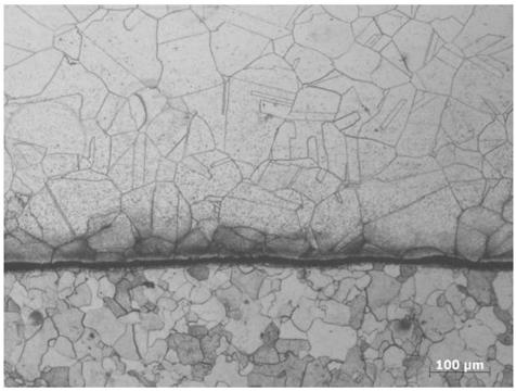
[0007] The purpose of the present invention is to provide a third-generation nuclear power plant high-shear strength extra-thick composite steel plate and its manufacturing method. Based on the performance requirements of the third-generation nuclear power plant composite steel plate, it is designed in terms of composite plate blank formation and vacuum degree. Advanced heating, rolling and heat treatment process, so as to ensure that the performance of the steel plate in different states meets the requirements, and solve the problem of low shear strength of extra-thick composite plate, difficult control of plate shape during quenching and tempering heat treatment, low production efficiency and high vacuum degree requirements The production difficulty caused by the problem is that the steel plate is 100% bonded, the shear strength of the steel plate is ≥ 400MPa, the shape of the steel plate is well controlled and the heat treatment cycle is shortened

Method used


Image

  • High-shear-strength super-thick composite steel plate for generation III nuclear power station and manufacturing method of composite steel plate
  • High-shear-strength super-thick composite steel plate for generation III nuclear power station and manufacturing method of composite steel plate
  • High-shear-strength super-thick composite steel plate for generation III nuclear power station and manufacturing method of composite steel plate

Examples


Embodiment Construction

[0028] The following examples are used to specifically illustrate the contents of the present invention, and these examples are only general descriptions of the contents of the present invention, and do not limit the contents of the present invention.

[0029] The chemical composition of the clad plate is shown in Table 1; the specifications of the clad billet are shown in Table 2; the rolling process of the clad plate is shown in Table 3; the heat treatment process of the clad plate is shown in Table 4; the mechanical properties of the clad plate are shown in Table 4. Table 5; the impact performance of the composite plate is shown in Table 6.

[0030] The chemical composition (wt%) of table 1 composite plate

[0031]

[0032] Table 2 Specifications of Composite Blanks

[0033] Example

Carbon steel intermediate billet thickness / mm

304L stainless steel intermediate billet thickness / mm

1

125

20

2

175

20

3

195

15

4

...


PUM


Abstract

The invention discloses a high-shear-strength super-thick composite steel plate for a generation III nuclear power station and a manufacturing method of the composite steel plate. The composite steelplate consists of steel-plate carbon steel and 304L austenitic stainless steel. The assembly sequence is as the follows from top to bottom: stainless steel, carbon steel, an isolating agent, carbon steel and stainless steel. Edge sealing is carried out on four edges of a combined billet by welding, vacuumizing treatment is carried out, and the vacuum degree is 100 Pa or lower. The heating temperature of the combined billet is 1200-1270 DEG C, the heating time is 10-15 hours, the single-stroke reduction rate is 5%-15%, the final rolling temperature is controlled to be 1050 DEG C or above, tempering heat treatment is carried out after rolling, the quenching temperature is 870-930 DEG C, the heat preservation time is 2-4 min / mm, and the heating rate is 1.0-1.5 min / mm. The tempering temperature is 620-660 DEG C, the heat preservation time is 3-6 min / mm, and the heating rate is 1.5-2.0 min / mm. The thickness of a finished composite steel plate is 29-110 mm, the shearing strength is good, andthe requirement of steel for composite boards of a nuclear power station is met.

Description

technical field [0001] The invention belongs to the technical field of metal composite plate production, and in particular relates to a composite steel plate for nuclear power and a manufacturing method thereof. Background technique [0002] Heterogeneous composite steel plate is a new type of economical material. The heterogeneous composite plate is made of stainless steel and carbon steel combined in a specific way. It has both the mechanical properties of carbon steel and the anti-corrosion properties of stainless steel. Traditional heterogeneous composite panels combine stainless steel and carbon steel by means of explosion. This process currently has many disadvantages. First of all, its production environment is greatly restricted. Generally, the production site needs to be selected in remote mountainous areas. Production and transportation cause greater difficulty; secondly, the large amount of explosives required for the explosion is more harmful to the environment, ...

Claims


Application Information

Patent Timeline
IPC IPC(8): B32B15/01B32B15/18B32B37/06B32B37/10C22C38/04C22C38/02C22C38/06C22C38/58C22C38/44C22C38/46C22C38/42C21D8/02
CPCB32B15/011B32B15/18B32B37/06B32B37/1018C21D8/0205C21D8/0226C21D8/0247C22C38/02C22C38/04C22C38/06C22C38/42C22C38/44C22C38/46C22C38/58
Inventor 颜秉宇孙殿东王长顺胡海洋王爽刘祥李文斌李广龙胡昕明王储
Owner ANGANG STEEL CO LTD
Why Eureka
Eureka Blog
Learn More