
A low-stress clamping method for overlapping parts facing bosses

A low-stress, clamping technology, applied in the field of parts pressing, can solve problems such as unreasonable pressing sequence of bosses, low processing quality of parts, accumulation of clamping stress, etc., to achieve clear guidance, reduce instability, and reduce loading The effect of clamping stress

Active Publication Date: 2020-09-11
CHENGDU AIRCRAFT INDUSTRY GROUP
View PDF4 Cites 0 Cited by
  • Summary
  • Abstract
  • Description
  • Claims
  • Application Information

AI Technical Summary

Problems solved by technology

[0004] The purpose of the present invention is to solve the problem that the clamping stress is continuously accumulated due to the unreasonable pressing sequence of the bosses during the clamping process of the parts overlapped by the bosses, and the excessive clamping stress affects the processing quality of the parts. A low-stress clamping method for overlapping parts facing bosses

Method used


Image

  • A low-stress clamping method for overlapping parts facing bosses
  • A low-stress clamping method for overlapping parts facing bosses
  • A low-stress clamping method for overlapping parts facing bosses

Examples


Embodiment 1

[0030] The present invention is a low-stress clamping method for overlapping parts facing bosses, comprising the following steps:

[0031] Step 1. According to the structural characteristics of the part, select the long direction of the part as the main direction of clamping;

[0032] Step 2. Select the leftmost boss in the main direction as the clamping starting point;

[0033] Step 3. Select the boss closest to the starting point of clamping as the clamping point;

[0034] Step 4. Calculate the distance between the boss whose clamping sequence is not determined and the clamping start point and the clamping point, and use the boss with the smallest sum of distances from the clamping point and the initial clamping point as the clamping point;

[0035] Step 5. Select a new clamping starting point on the other side of the part corresponding to the clamping point. The starting point is the first boss on the other side of the part in the clamping direction whose clamping sequence...

Embodiment 2

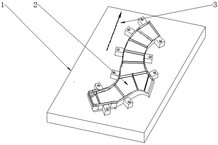
[0038] Such as figure 1 , figure 2 The part 2 shown is a grooved part, and the part is fixed by adding process bosses. Considering its structural characteristics and processing scheme, 10 bosses are set for compaction, and the positions of the bosses are symmetrically distributed. The size of the bosses is determined according to the Determined by part thickness and length.

[0039] Establish the clamping sequence as follows:

[0040] Step 1. Take the long direction 3 of the part as the main direction of part clamping, and select the boss 4 located on the leftmost side of the main direction as the starting point A of clamping 0 ;

[0041] Step 2. Calculate the boss 5-13 and the starting point A of the clamping in sequence 0 The distance will be with the clamping starting point A 0 The boss 13 with the smallest distance is used as the clamping point A 1 , to establish the initial clamping order sequence O 1 ={4 , 13};

[0042] Step 3. Calculate the distances between a...


PUM


Abstract

The invention discloses a low stress clamping method for lap joint of a part by facing a boss. The method comprises the steps of selecting a proper position and arranging a process boss of a certain shape and size according to the features of the part shape and outline; and fixing the relative position between the boss and a working table by screws, and then tightening the screws in a special direction and sequence, so that the part is fit with a working platform, and the clamping of the part is finished. The low stress clamping method is applicable for clamping and pressing a locating part through the boss externally connected, and the clamping stress generated in the clamping process of the part can be reduced effectively; and the influence of the clamping process on the machining precision of the part is reduced, and meanwhile the clamping efficiency of the part can be further improved.

Description

technical field [0001] The invention relates to a method for pressing parts, in particular to a method for pressing parts that are clamped by overlapping bosses. A low-stress clamping method in which the boss generates additional force on the part, resulting in excessive clamping stress. Background technique [0002] Clamping and positioning is one of the most basic and important processes in parts processing, which has an extremely important impact on the processing accuracy and quality of parts. At this stage, when processing parts, the method of external process bosses is usually used to fix the parts and tooling to achieve stable clamping. The method of external boss has the characteristics of strong versatility and simple design, and is currently the most widely used clamping method. However, this method will generate additional clamping stress. After removing the boss, the part is prone to deformation and affects Processing quality. [0003] The process boss is conn...

Claims


Application Information

Patent Timeline
Patent Type & Authority Patents(China)
IPC IPC(8): B23Q3/06
CPCB23Q3/062
Inventor 黄方林王绍江罗广权胡颖晓
Owner CHENGDU AIRCRAFT INDUSTRY GROUP
Learn More