
A cable connection with shielding continuity

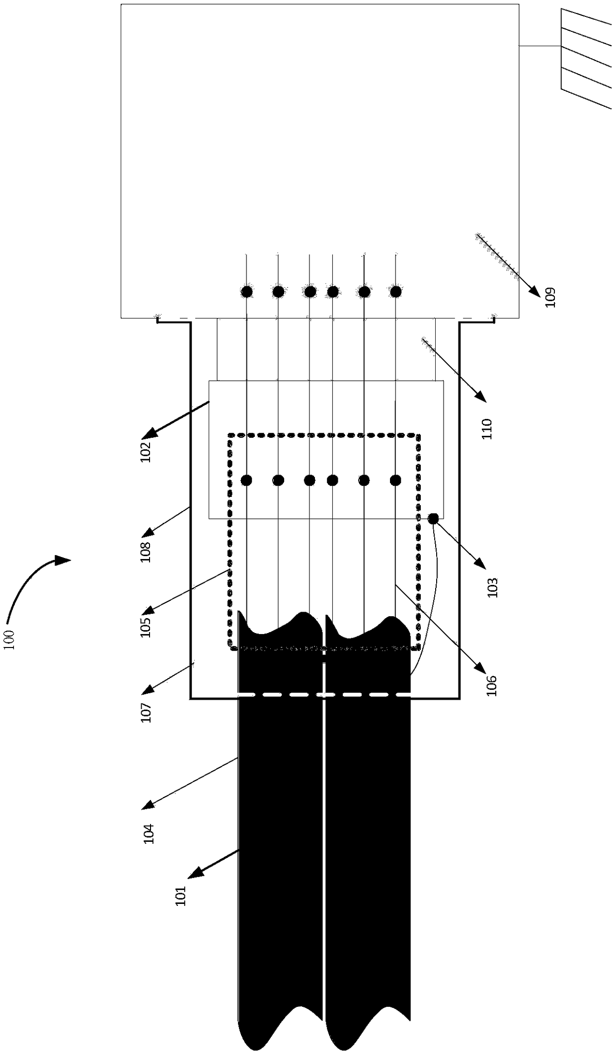
A technology of cable connection and cable connector, which is applied in the field of satellite cable signal transmission, can solve problems such as difficulty in application, inability to meet shielding performance, inability to replace connectors, etc., and achieve the effect of light weight

Active Publication Date: 2018-12-11
SHANGHAI ENG CENT FOR MICROSATELLITES
View PDF5 Cites 4 Cited by
  • Summary
  • Abstract
  • Description
  • Claims
  • Application Information

AI Technical Summary

Problems solved by technology

[0010] (1) In order to prevent the tail wire of the anti-wave bushing from piercing the cable insulation layer (it has happened many times), usually it is necessary to end the shielding at about 5cm outside the cable, and deal with the tail wire so that the shielding cannot be continuous
For transmission cables with low frequency signals and relatively high sensitivity, this connection method cannot meet the requirements of shielding effectiveness
[0011] (2) Use the shielding card (tail cover) to ground the shielding layer, which can meet the requirements of shielding continuity, but this tail cover is a special tail cover, not all connectors can be installed with this tail cover, and it is often found that the signal is easy to When disturbed, it is impossible to replace the connector, and the tail cover is very long, which requires a high plug-in space, and it is usually difficult to apply to satellites with a compact layout

Method used


Image

  • A cable connection with shielding continuity
  • A cable connection with shielding continuity
  • A cable connection with shielding continuity

Examples


Embodiment Construction

[0032] It should be noted that components in the various figures may be shown exaggerated for the purpose of illustration and are not necessarily true to scale. In the various figures, identical or functionally identical components are assigned the same reference symbols.

[0033] In the present invention, unless otherwise specified, "arranged on", "arranged on" and "arranged on" do not exclude the presence of intermediates between the two.

[0034] In the present invention, each embodiment is only intended to illustrate the solutions of the present invention, and should not be construed as limiting.

[0035] In the present invention, unless otherwise specified, the quantifiers "a" and "an" do not exclude the scene of multiple elements.

[0036] It should also be pointed out here that in the embodiments of the present invention, for the sake of clarity and simplicity, only a part of parts or components may be shown, but those skilled in the art can understand that under the t...


PUM


Abstract

The invention relates to a cable connection with shielding continuity, which comprises a cable, a cable connector, a shielding layer ground wire, a connector tail clip, a copper cloth, a heat shrinkable film, a copper foil adhesive tape, a polyimide adhesive tape and a box. Shielding between a shielding uncovering part and a connector is realized by using a metal cover such as a copper cloth, so that 360 degree sealed overlapping connection between the shielding layer and the electrical connector is realized; The shielding integrity of the whole signal transmission path is realized by coveringthe gap between the connector and the chassis and between the chassis and the chassis with a plastic and sticky metal cover such as copper foil adhesive tape. The cable connection according to the invention can remarkably reduce the electromagnetic leakage between the cable and the connector and between the connector and the box, thereby realizing comprehensive and continuous electromagnetic shielding of the entire signal transmission path, and solving the problem that the traditional shielding by means of a shielding card or the tail cover needs extra weight and mounting space.

Description

technical field [0001] The present invention relates to satellite cable signal transmission, in particular to a cable connection with shielding continuity. Background technique [0002] As an important part of electronic signal transmission, transmission cables and electrical connectors should have good transmission characteristics and electromagnetic compatibility. As the signal transmission path, electrical connectors and shielded cables should form a completely closed Faraday cage to ensure the continuity of electromagnetic shielding, thereby enhancing shielding effectiveness. The shielding continuity mainly depends on the terminal connection of the shielded cable, and the shielding layer and the rear shell of the electrical connector form a 360° closed lap to avoid electromagnetic leakage. The current termination methods mainly include the following types: [0003] (1) using shielding card [0004] Lay the cables to the wiring points, compare the wiring length, and le...

Claims


Application Information

Patent Timeline
IPC IPC(8): H01R24/00H01R13/6581H01R13/6591H01R13/648
Inventor 陈博张芮朱野刘阔丰正功汪灏闫梅曹彩霞李静
Owner SHANGHAI ENG CENT FOR MICROSATELLITES
Learn More