Chemical smoke efficient absorption device
An absorption device and flue gas technology, applied in the direction of gas treatment, chemical instruments and methods, membrane technology, etc., can solve the problem that the absorption liquid cannot be fully contacted, the flue gas absorption effect is not good, and the flue gas cannot be fully purified and other problems, to achieve the effect of increased base area, ingenious structure and reasonable design
- Summary
- Abstract
- Description
- Claims
- Application Information
AI Technical Summary
Problems solved by technology
Method used
Image
Examples
Embodiment 1
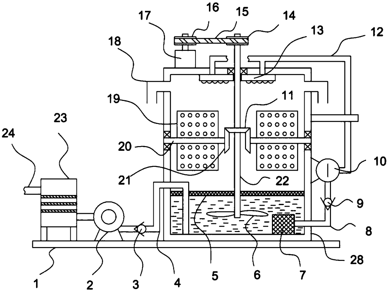
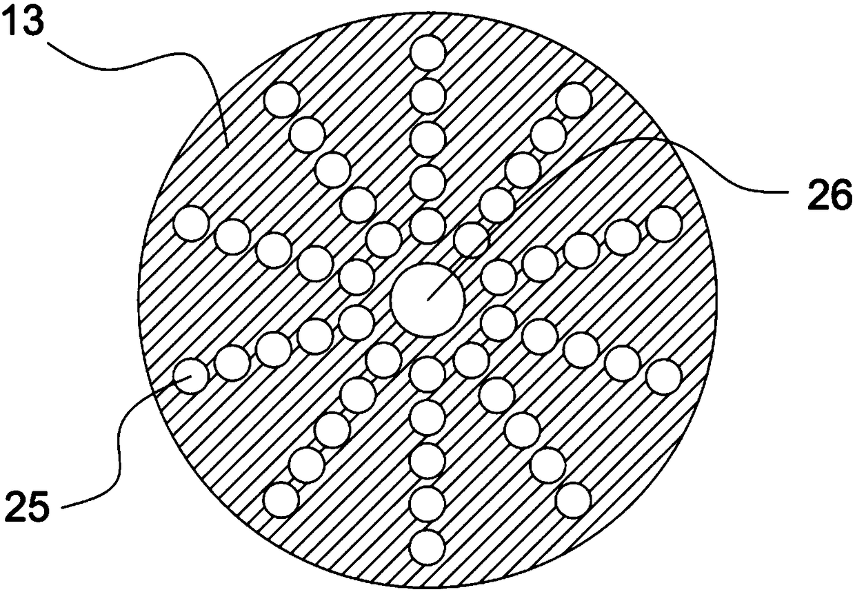
[0023] see Figure 1-3 , a kind of high-efficiency absorption device for chemical flue gas, comprising a base plate 1, an absorption box 28 is fixedly installed on the base plate 1, and an absorption liquid is filled in the absorption box 28, and a dust collection box 23 is fixedly installed on the base plate 1 and connected to it through a pipeline Connected air pump 2, the outlet end of the air pump 2 is connected with the conveying pipe 4 extending to the inner bottom of the absorption box 28, the top of the absorption box 28 is fixedly installed with a drive motor 17, and the output shaft of the drive motor 17 is coaxial A driving pulley 16 is fixedly installed, and a driving shaft 22 is vertically penetrated in the absorption box 28. The surface of the driving shaft 22 is sleeved and fixedly installed with a flat belt 15 connected to the driving pulley 16 through a flat belt 15. The lower end of the shaft 22 extends below the liquid level of the absorption liquid in the a...
Embodiment 2
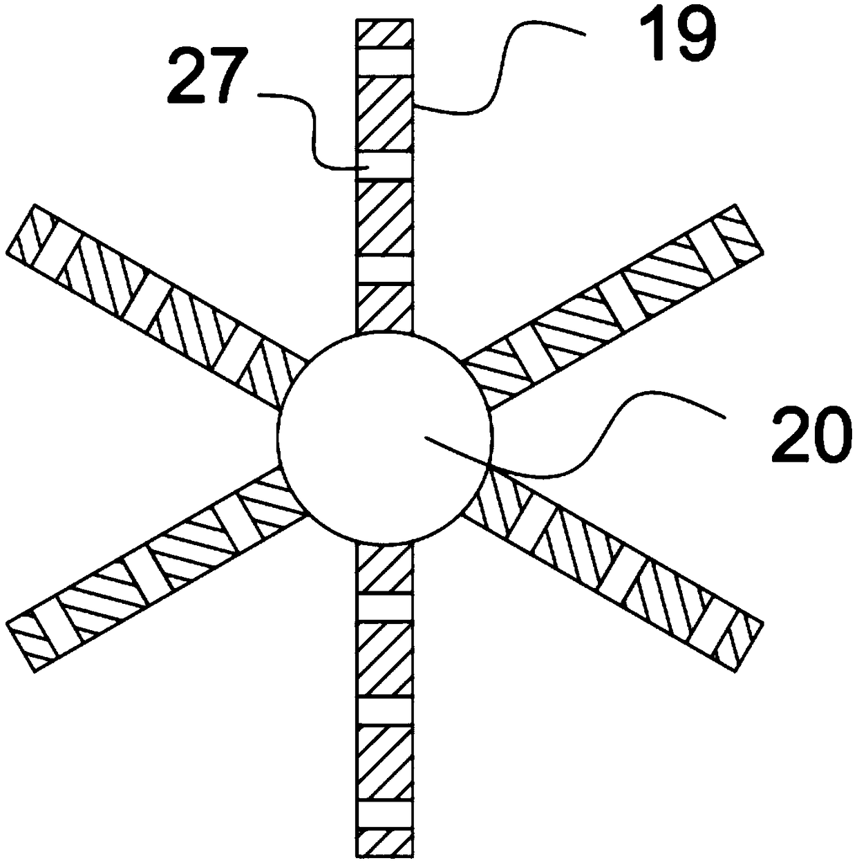
[0029] On the basis of Embodiment 1, a dispersing device is provided in the absorption box 28, and the dispersing device includes two symmetrically arranged driven shafts 20 that are rotated and horizontally installed in the absorption box 28, and the surface of the driven shaft 20 is uniform in ring shape. Several dispersing plates 19 are fixedly installed, and several dispersing mesh holes 27 are opened on the dispersing plate 19. The driven shaft 20 is coaxially fixed with a driven bevel gear 21 near the end of the driving shaft 22, and the surface of the driving shaft 22 is sleeved and fixedly installed. There is a driving bevel gear 11 meshingly connected with the driven bevel gear 21; while the driving shaft 22 rotates, the driving shaft 22 drives the driving bevel gear 11 to rotate, and the driving bevel gear 11 drives the driven bevel gear 11 through the driven bevel gear 21 meshing with it. The moving shaft 20 rotates, and the driven shaft 20 drives the dispersing plat...
PUM
 Abstract
Description
Claims
Application Information
 - R&D
- Intellectual Property
- Life Sciences
- Materials
- Tech Scout
- Unparalleled Data Quality
- Higher Quality Content
- 60% Fewer Hallucinations
Browse by: Latest US Patents, China's latest patents, Technical Efficacy Thesaurus, Application Domain, Technology Topic, Popular Technical Reports.
© 2025 PatSnap. All rights reserved.Legal|Privacy policy|Modern Slavery Act Transparency Statement|Sitemap|About US| Contact US: help@patsnap.com


