
Structure for preventing LED conductive adhesive from loosening during soldering or use

A conductive adhesive and loosening technology, which is applied in the direction of circuits, electrical components, semiconductor devices, etc., can solve problems such as the lack of adhesive force of conductive adhesives and the inability of LED chips to continue to work, so as to reduce the number of rework of finished products and solve the effect of unqualified rate

Pending Publication Date: 2018-12-07
ZHONGSHAN JINGDE OPTOELECTRONICS
View PDF0 Cites 1 Cited by
  • Summary
  • Abstract
  • Description
  • Claims
  • Application Information

AI Technical Summary

Problems solved by technology

[0003] Due to environmental protection and cost constraints in the LED manufacturing process, the amount of silver layer used in the current LED bracket is gradually reduced during electroplating to make it thinner and thinner. In order to prevent the substrate in the silver layer from being affected by oxidation For LED use, in the existing electroplating technology, an anti-silver oxidant will be added to the silver layer on the surface of the crystal-bonding area, but the anti-silver oxidizer will solidify the crystal when the LED is not completely volatilized before production, which will cause chemical substances in the conductive adhesive It reacts with the anti-silver oxidant, and the result is that the adhesive force of the conductive adhesive is lost. In the subsequent high-temperature process or during daily use, the LED chip will be unable to continue to work due to the loosening of the conductive adhesive from the die-bonding area. This is a cost issue for production and a quality issue for users

Method used


Image

  • Structure for preventing LED conductive adhesive from loosening during soldering or use
  • Structure for preventing LED conductive adhesive from loosening during soldering or use
  • Structure for preventing LED conductive adhesive from loosening during soldering or use

Examples


Embodiment Construction

[0025] In order to make the technical means, creative features, objectives and effects of the present invention easy to understand, the present invention will be further described below in conjunction with specific embodiments.

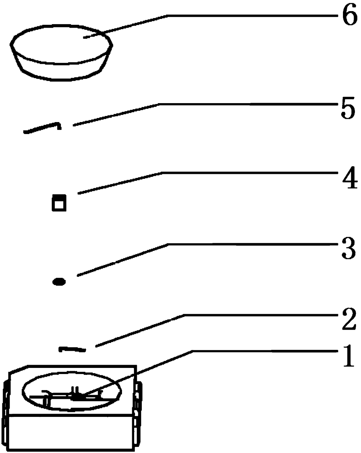
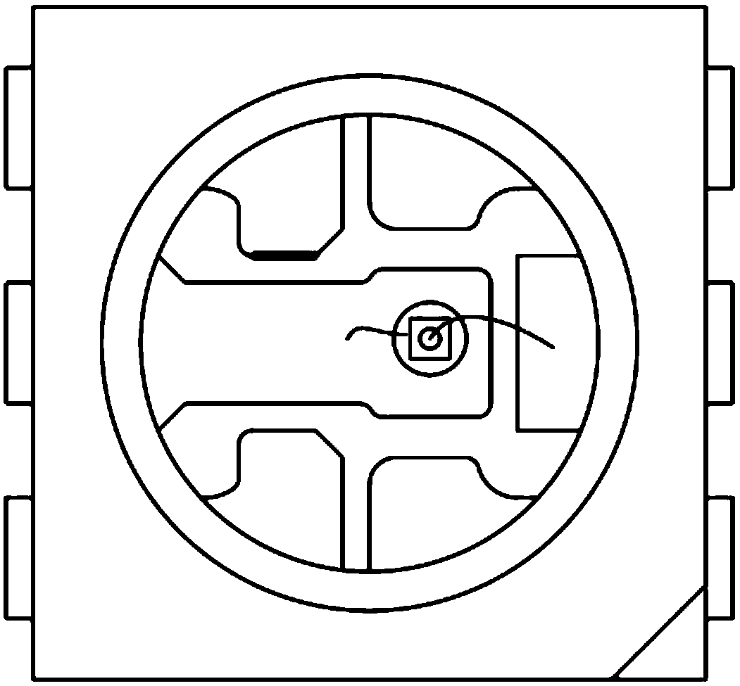
[0026] refer to figure 1 , this specific embodiment adopts the following technical solutions: a structure to prevent the LED conductive adhesive from loosening during welding or use, which is characterized in that it includes a bracket bowl cup (1), a cup bottom wire (2), conductive adhesive (3), LED chips (4), wires (5), and encapsulation glue (6), the bracket cup (1) is fixed with a crystal-bonding area plate inside; the conductive glue (3) is arranged on the crystal-bonding area plate; One end of the cup bottom wire (2) is welded on the die-bonding area plate, and the other end is placed inside the conductive glue (3); the bottom of the LED chip (4) is placed in the conductive glue (3); the wire (5) ) one end is welded on the top of the LED chip (...


PUM


Abstract

The invention discloses a structure for preventing LED conductive adhesive from loosening during soldering or use and relates to the field of LED manufacturing. The structure is characterized by comprising a bracket bowl cup, a cup bottom wire, the conductive adhesive, an LED wafer, a wire and packaging adhesive. At present, for preventing a substrate in a silver layer from affecting use of an LEDdue to oxidation, many manufacturers increase the anti-silver oxidant on the silver layer on a surface of a solid crystal region plate through the existing electroplating technology, however, the anti-silver oxidant solidifies when the anti-silver oxidant does not completely volatilize before the LED is produced, which causes chemical substances in the conductive adhesive to react with the anti-silver oxidant, in the subsequent high-temperature process or daily use, a problem that the LED wafer can not continue to work due to the conductive adhesive loosening away from the solid crystal region plate occurs. For solving the problem, a medium capable of connecting the conductive adhesive and the solid crystal region plate and realizing conduction is added between the conductive adhesive andthe solid crystal region plate, even if the LED wafer is disengaged from the solid crystal region plate due to the lack of adhesion of the conductive adhesive, such a problem of an open dead lamp does not occur.

Description

technical field [0001] The invention belongs to the field of LED manufacturing, and in particular relates to a structure for preventing the LED conductive glue from loosening during welding or use. Background technique [0002] Light-emitting diode (LIGHT EMITING DIODE, referred to as LED), is a semiconductor solid light-emitting device. It uses a solid semiconductor chip as a light-emitting material. When a forward voltage is applied to both ends, the minority interceptors and majority interceptors in the semiconductor recombine , release excess energy to cause photon emission, and directly emit red, orange, yellow, green, cyan, blue, purple light. Due to the advantages of high energy saving, long life, and environmental protection, LED light sources have become more and more widely used. The advantages of environmental protection and energy saving make LEDs be regarded as one of the main lighting sources in the 21st century. [0003] Due to environmental protection and co...

Claims


Application Information

Patent Timeline
IPC IPC(8): H01L33/62
CPCH01L33/62
Inventor 张鹏邵先喜
Owner ZHONGSHAN JINGDE OPTOELECTRONICS
Learn More