
Total voltage detection circuit and method of high-voltage battery system

A high-voltage battery and detection circuit technology, applied in the direction of measuring electricity, measuring devices, measuring electrical variables, etc., can solve the problems of increasing static power consumption of the battery, insufficient accuracy of the total voltage, and inaccurate detection accuracy of the total voltage of the battery system, etc.

Inactive Publication Date: 2018-12-07
SUNWODA ELECTRIC VEHICLE BATTERY CO LTD
View PDF11 Cites 7 Cited by
  • Summary
  • Abstract
  • Description
  • Claims
  • Application Information

AI Technical Summary

Problems solved by technology

During the use of the battery system, the total voltage detection accuracy of the battery system is inaccurate due to the influence of temperature changes, humidity changes, corrosion, device aging and inconsistent parameters of the device itself.
[0003] There are two existing total voltage detection methods, one is that the resistors are connected across the positive and negative terminals of the total battery voltage, and the other is that the positive and negative terminals of the total battery voltage divide the voltage respectively to the ground. However, these two methods There are high requirements on the resistance and precision of the imported resistors. According to the national standard, the progress of resistors with a resistance of 1 megohm should not exceed 0.5%. If the imported resistors are too small, the static power consumption of the battery will be increased. If it is too large, it will affect the acquisition accuracy of the total voltage, and there is no suitable resistor on the market at present, so the total voltage measured by the existing two methods is not accurate enough

Method used


Image

  • Total voltage detection circuit and method of high-voltage battery system
  • Total voltage detection circuit and method of high-voltage battery system
  • Total voltage detection circuit and method of high-voltage battery system

Examples


Embodiment Construction

[0029] The realization, functional characteristics and advantages of the present invention will be further described in conjunction with specific embodiments and with reference to the accompanying drawings. It should be understood that the specific embodiments described here are only used to explain the present invention, not to limit the present invention.

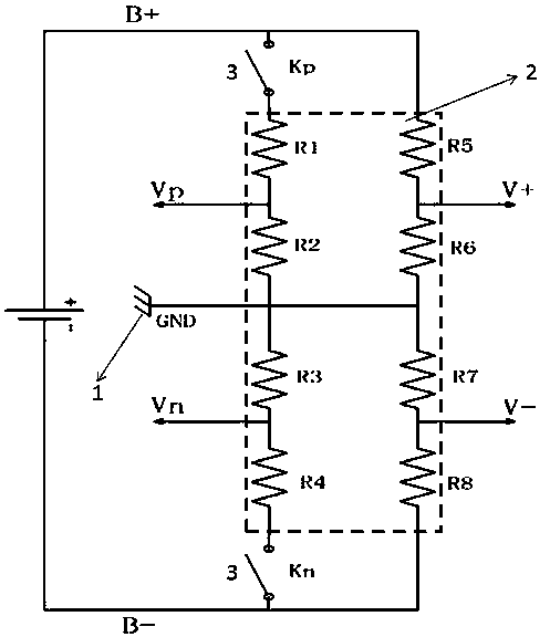
[0030] Such as figure 1 As shown, the detection circuit and detection method of the total voltage of a high-voltage battery system provided by the present invention include the positive (B+), negative (B-) of the high-voltage battery system, the ground (1), the detection resistor network (2) and the high-voltage switch (3). The detection resistor network (2) includes a resistor 1, a resistor 2, a resistor 3, a resistor 4, a resistor 5, a resistor 6, a resistor 7, and a resistor 8, and the resistance values ​​are all known, which are respectively R1, R2, R3, R4, R5, R6, R7, R8, the high voltage switch (3) includes a swi...


PUM


Abstract

The invention provides a total voltage detection circuit and method of a high-voltage battery system. The circuit comprises an anode and cathode of the system, the ground, the detection resistor network and a high voltage switch. The detection resistor network comprises first to eight resistors, the resistance of each resistor is known, and the high voltage switch comprises a switch Kp and a switch Kn. Voltage are sampled from different electric loops formed by different serial / parallel connection manners to obtain voltage values of the different resistors, a voltage ratio alpha parameter generated by low-resistance high-precision resistors is used to correct a voltage ratio beta generated by the high-resistance low-precision resistors, an Ohm law is combined to calculate the total voltagevalue, the method is simple in operation and easy to realize, the total voltage value of higher precision can be obtained in any environmental condition, and the insulation performance of the batterymanagement system can be ensured.

Description

technical field [0001] The invention relates to a voltage detection method for a new energy power battery system, in particular to a detection circuit and a detection method for the total voltage of a high-voltage battery system. Background technique [0002] The high energy density of power lithium-ion batteries makes them the main source of power for new energy vehicles. However, due to differences in production processes and usage environments, the inconsistency of battery packs gradually expands during use, and overcharging, overdischarging and The danger of local overheating seriously affects the service life and safety of the battery pack. The battery management system (BMS) is a control system that protects the safe use of power lithium-ion batteries. It monitors the use status of the batteries at all times, and takes necessary measures to alleviate the inconsistency of the battery pack, providing guarantee for the safety of new energy vehicles. In the battery manage...

Claims


Application Information

Patent Timeline
IPC IPC(8): G01R31/36
Inventor 王华文曾志平雷晶晶唐智梁锐
Owner SUNWODA ELECTRIC VEHICLE BATTERY CO LTD
Learn More