A non-destructive detection method for buried concrete early-frozen ice
A non-destructive testing and concrete technology, which is applied in measuring devices, instruments, investigation stages/state changes, etc., can solve the problems of evaluating the early freezing damage of negative temperature concrete, which has not yet been found, and achieves easy operation, accurate and reliable measurement methods. , the effect of low cost
- Summary
- Abstract
- Description
- Claims
- Application Information
AI Technical Summary
Problems solved by technology
Method used
Image
Examples
specific Embodiment approach 1
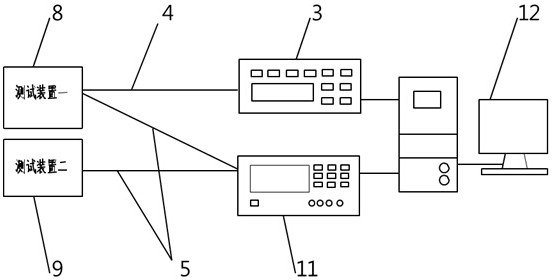
[0039] Specific implementation mode one: as Figure 1-Figure 3 As shown, a non-destructive detection method for embedded concrete early frozen ice, said method is realized based on temperature tester 3, resistivity tester 11 and two test devices, said two test devices are testing Device one 8 and test device two 9;
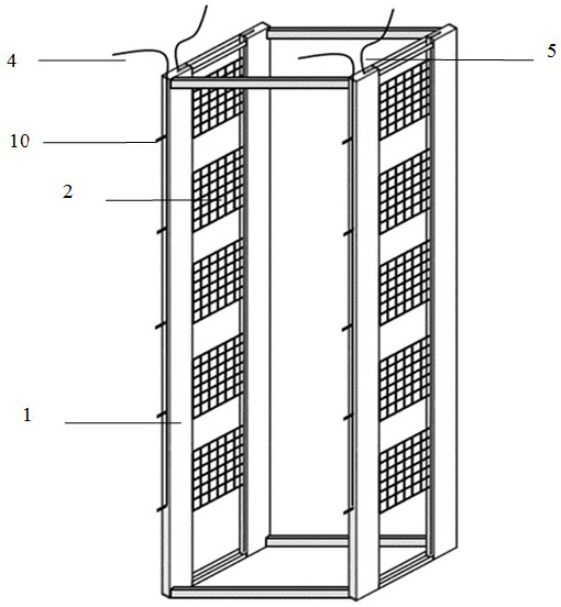
[0040] Described testing device one 8 and testing device two 9 all comprise quadrangular prism frame 1, and described testing device one 8 also comprises a plurality of thermocouples 4 and many pairs of electrode nets 2, and described testing device two 9 also comprises a pair of electrode nets 2;
[0041] The specific structure of the test device-8 is: two opposite sides in the quadrangular prism frame 1 are respectively fixed with multiple pairs of electrode nets 2, and the plurality of pairs of electrode nets 2 are arranged from top to bottom, each pair of electrode nets 2 All connect lead 5, and the other end of described lead 5 is connected with described r...
specific Embodiment approach 2
[0051] Specific implementation mode two: as Figure 1-Figure 3 As shown, this embodiment is a further description of the specific embodiment one. The distance between each pair of electrode nets 2 in the test device one 8 and the test device two 9 should be at least greater than 3 times the maximum aggregate particle size of the concrete. times (the spacing, size and material of each pair of electrode nets 2 in the test device 2 9 are the same as those of the test device 1 8, so as to avoid the influence caused by different settings), so as to avoid the contingency caused by the existence of large concrete aggregates to the test data Impact.
specific Embodiment approach 3
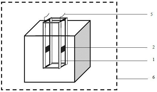
[0052] Specific implementation mode three: as figure 1 , image 3 As shown, this embodiment is a further description of specific embodiment one or two. The installation position of the pair of electrode grids 2 in the test device two 9 should be located in the middle of the control group concrete specimen 7, and the The size of the control group concrete specimen 7 should be at least 3 times the size of the concrete block between the pair of electrode grids 2, so that the range of the transmission path of the current in the device two 9 is the same as the range of the transmission path of the device one 8, because The transmission of ions is not only directly transmitted through the concrete between the electrode grid pairs, but also extends to a certain space outside the concrete.
PUM
 Abstract
Description
Claims
Application Information
 - R&D Engineer
- R&D Manager
- IP Professional
- Industry Leading Data Capabilities
- Powerful AI technology
- Patent DNA Extraction
Browse by: Latest US Patents, China's latest patents, Technical Efficacy Thesaurus, Application Domain, Technology Topic, Popular Technical Reports.
© 2024 PatSnap. All rights reserved.Legal|Privacy policy|Modern Slavery Act Transparency Statement|Sitemap|About US| Contact US: help@patsnap.com


