
Robot rapid tool changing self-adaptive force control tail end executing device design

A technology of end effector and adaptive controller, which is applied in the direction of automatic grinding control devices, manipulators, grinding machine tools, etc., to achieve the effect of ensuring machining accuracy

Inactive Publication Date: 2018-12-07
CHONGQING UNIV
View PDF5 Cites 2 Cited by
  • Summary
  • Abstract
  • Description
  • Claims
  • Application Information

AI Technical Summary

Problems solved by technology

At present, there is a lack of a better processing method. The problems in the processing need to use a method that can realize fast and accurate tool change, and monitor the grinding force on the front end of the grinding head in real time through the arrangement of mechanical sensors, and carry out the grinding path. Real-time adjustment to achieve high-precision adaptive grinding automatic grinding robot to solve

Method used


Image

  • Robot rapid tool changing self-adaptive force control tail end executing device design
  • Robot rapid tool changing self-adaptive force control tail end executing device design
  • Robot rapid tool changing self-adaptive force control tail end executing device design

Examples


Embodiment Construction

[0044] The working principle of the present invention is as follows:

[0045] Before grinding, the standby end effector and the standby tool are placed at the coordinate positions set in advance in the mechanical arm grinding numerical control system. Start the mechanical arm, and the mechanical arm automatically moves to the first docking point, and the end effector is realized through the process of infrared recognition (32), mechanical claw (34) clamping and bolt fastening, and pipe docking point (17) docking. capture. After capturing the end effector, the robotic arm automatically moves to the next docking site to capture the grinding tool. When the tool handle triggers the infrared sensing device, it indicates that the tool has reached the clamping position. At this time, the three pressure adaptive controllers (36) tighten the tool through the action of the pressure control cylinder. After capturing the end effector and the corresponding machining tool, the robotic arm...


PUM


Abstract

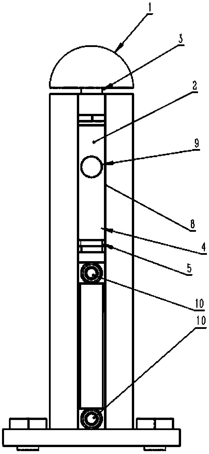
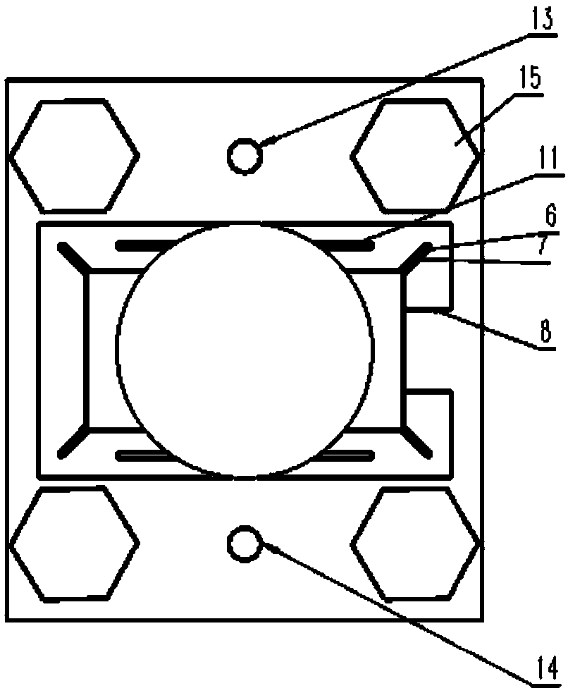
The invention discloses a robot rapid tool changing self-adaptive force control tail end executing device design. The control tail end executing device design comprises a hemispherical clamping device, a Z-shaped tension sensor, a pressure control air cylinder, an interface device between a tail end actuator and a mechanical arm. The hemispherical clamping device, the Z-shaped pulling pressure optical sensor and the pressure control air cylinder are divided into an upper part, a middle part, and a lower part to form a pressure self-adaptive controller and a core part, and the pressure self-adaptive controller and the core part are connected and arranged as a whole; the set constraint effect of the pipe butt joint position points achieves butt joint and solid connection of the data line andthe air pipe, that is the soft tubular objects. According to the tube butt joint position points, and the data lines and the air pipes extending out of each pressure self-adaptive controller are orderly integrated into the butt joint plane for butt joint; a central bevel gear is adopted at the joint of the tail end executor to drive a surrounding bevel gear to rotate and tighten a fixing bolt andan air hole interface, and the position of the tail end executor is fixed at the same time to realize the connection of the air pipes. The robot rapid tool changing self-adaptive force control tail end executing device design has the advantages that clamping and detecting force control operation is integrated and real-time three-dimensional force control is achieved.

Description

[0001] manual technical field [0002] The invention relates to a multifunctional self-adaptive end effector for rapid tool change by a robot, in particular, automatic grinding and processing of a booster stage inlet rectifier by a robot. Background technique [0003] In the past 20 years, the application of grinding technology in aerospace, transportation machinery, shipbuilding, metallurgy, chemical industry and energy has become more and more extensive. At the same time, with the continuous development and progress of the manufacturing industry, the requirements for product processing accuracy are getting higher and higher, and a series of mechanical automation processing problems of high-precision parts are gradually exposed. [0004] Take the processing of supercharged imported rectifiers as an example to explain in detail. The supercharged inlet rectifier is an important part of the supercharged fan components. It is a typical thin-walled, welded casing, which is comp...

Claims


Application Information

Patent Timeline
Patent Type & Authority Applications(China)
IPC IPC(8): B24B51/00B24B49/00B24B45/00B25J11/00
CPCB24B45/006B24B49/00B24B51/00B25J11/0065
Inventor 肖贵坚黄云幸家正安子健王承新李冰岩
Owner CHONGQING UNIV
Learn More