
System and method for preparing oxygen by vacuum pressure swing adsorption

A technology of vacuum pressure swing adsorption and oxygen generation system, which is applied in separation methods, chemical instruments and methods, oxygen preparation, etc., can solve problems such as load adjustment, unfavorable optimization control, equipment impact, etc., to reduce noise and energy consumption, and effectively Facilitate adsorption operation and ensure stability

Pending Publication Date: 2018-12-07
CHENGDU HUAXITANG ENVIRONMENTAL PROTECTION TECH CO LTD
View PDF1 Cites 8 Cited by
  • Summary
  • Abstract
  • Description
  • Claims
  • Application Information

AI Technical Summary

Problems solved by technology

[0005] 1. The noise is high, and it is necessary to isolate the overall noise of the factory building. At the same time, it is necessary to solve the contradiction between noise isolation and ventilation, which is neither environmentally friendly nor increases investment;
[0006] 2. The vibration is large, and the Roots equipment has a large vibration. It is necessary to make anti-seismic design for the pipeline connected to it, which will increase unnecessary technical difficulty and investment;
[0007] 3. High energy consumption. The thermal efficiency of Roots equipment is usually only about 60%. Compared with other advanced gas compression equipment, the energy consumption is relatively large;
[0008] 4. It is not conducive to optimal control. The PSA oxygen production process will show periodic fluctuations. Roots equipment cannot actively adjust to this changing working condition. Due to the inherent characteristics of Roots equipment, when fluctuations occur, they are usually passively borne , but it will often cause a greater impact on the equipment, thereby affecting the overall life and reliability of the equipment. For example, when the oxygen production load needs to be reduced, the Roots equipment can hardly use frequency conversion equipment to adjust the load on large oxygen production equipment. Only the excess oxygen can be vented, resulting in unnecessary waste. Without pressure equalization treatment for Roots equipment, it is easy to cause pressure imbalance during operation, which will cause uneven oxygen concentration. If the top of the tank When the oxygen concentration is lower than that at the bottom, most of the product gas used in the cleaning process will be sucked away by the vacuum pump, that is, this part of the product body is wasted

Method used


Image

  • System and method for preparing oxygen by vacuum pressure swing adsorption
  • System and method for preparing oxygen by vacuum pressure swing adsorption

Examples


Embodiment 1

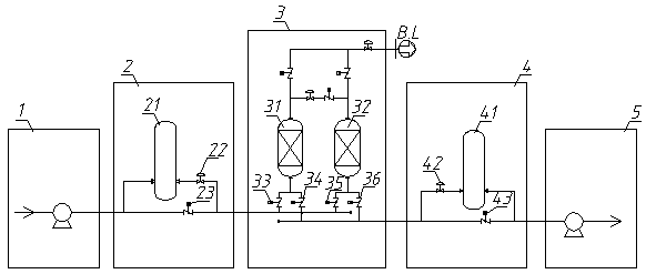
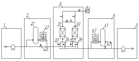
[0046] Such as figure 1 As shown, a vacuum pressure swing adsorption oxygen production system includes a rate fan 1, an adsorption separation unit 3 and a rate vacuum pump 5, and a fan worker is connected between the air inlet of the adsorption separation unit 3 and the rate fan 1 A condition control unit 2, a vacuum pump working condition control unit 4 is connected between the exhaust port of the adsorption separation unit 3 and the rate vacuum pump 5;

[0047] The fan operating condition control unit 2 includes a buffer tank A21, a control valve A22 and a valve A23. The buffer tank A21 is connected in series with the control valve A22 through a pipeline. The buffer tank A21 and the control valve A22 are connected in series and then connected in parallel with the valve A23. Both the control valve A22 and the valve A23 communicate with the air inlet of the adsorption separation unit 3;

[0048] The working condition control unit 4 of the vacuum pump includes a buffer tank B4...

Embodiment 2

[0053] Such as figure 1 As shown, a vacuum pressure swing adsorption oxygen production system includes a rate fan 1, an adsorption separation unit 3 and a rate vacuum pump 5, and a fan worker is connected between the air inlet of the adsorption separation unit 3 and the rate fan 1 A condition control unit 2, a vacuum pump working condition control unit 4 is connected between the exhaust port of the adsorption separation unit 3 and the rate vacuum pump 5;

[0054] The fan operating condition control unit 2 includes a buffer tank A21, a control valve A22 and a valve A23. The buffer tank A21 is connected in series with the control valve A22 through a pipeline. The buffer tank A21 and the control valve A22 are connected in series and then connected in parallel with the valve A23. Both the control valve A22 and the valve A23 communicate with the air inlet of the adsorption separation unit 3;

[0055] The working condition control unit 4 of the vacuum pump includes a buffer tank B4...

Embodiment 3

[0062] Such as figure 1 As shown, a vacuum pressure swing adsorption oxygen production system includes a rate fan 1, an adsorption separation unit 3 and a rate vacuum pump 5, and a fan worker is connected between the air inlet of the adsorption separation unit 3 and the rate fan 1 A condition control unit 2, a vacuum pump working condition control unit 4 is connected between the exhaust port of the adsorption separation unit 3 and the rate vacuum pump 5;

[0063] The fan operating condition control unit 2 includes a buffer tank A21, a control valve A22 and a valve A23. The buffer tank A21 is connected in series with the control valve A22 through a pipeline. The buffer tank A21 and the control valve A22 are connected in series and then connected in parallel with the valve A23. Both the control valve A22 and the valve A23 communicate with the air inlet of the adsorption separation unit 3;

[0064] The working condition control unit 4 of the vacuum pump includes a buffer tank B4...


PUM


Abstract

The invention relates to a system and method for preparing oxygen by vacuum pressure swing adsorption. The system comprises a velocity type fan, an adsorptive separation unit and a velocity type vacuum pump, wherein a fan work condition control unit is connected between the air inlet of the adsorptive separation unit and the velocity type fan; a vacuum pump work condition control unit is connectedbetween the exhaust of the adsorptive unit and the velocity type vacuum pump; prediction and adjustment can be carried out in advance by regulating the openness of a control valve A when pressure fluctuates, so that the influence caused by time delay of valve action can be eliminated; the inlet flow rate of the fan work condition control unit is equal to the outlet flow rate of the velocity typefan, the pressure of a buffer tank B is kept constant by controlling the flow rate of a valve B to be equal to the inlet flow rate of the vacuum pump, and the inlet flow rate and pressure of the velocity vacuum pump can be kept constant, so that the inlet pressure and outlet pressure are ensured to be smooth.

Description

technical field [0001] The invention belongs to the technical field of oxygen production equipment, and in particular relates to a vacuum pressure swing adsorption oxygen production system and method. Background technique [0002] The vacuum pressure swing adsorption oxygen production system uses a blower to boost the raw air and sends it into the adsorption tower, and uses different adsorbents filled in the adsorption tower to treat water (H2O), carbon dioxide (CO2) and Nitrogen (N2) is selectively adsorbed, and the unadsorbed oxygen (O2) becomes the product gas produced by the system; when the adsorbent is saturated, a vacuum pump is used to evacuate and depressurize the adsorption tower to make the water adsorbed by the adsorbent ( H2O), carbon dioxide (CO2) and nitrogen (N2) are desorbed, the adsorbent is regenerated, and a multi-tower cycle is used to obtain an oxygen-rich product with a higher oxygen concentration (60-93%). [0003] The patent number is CN201020580511...

Claims


Application Information

Patent Timeline
Patent Type & Authority Applications(China)
IPC IPC(8): B01D53/047B01D53/053C01B13/02
CPCB01D53/0476B01D53/053C01B13/0259Y02P20/151
Inventor 马光俊
Owner CHENGDU HUAXITANG ENVIRONMENTAL PROTECTION TECH CO LTD
Learn More