Eureka AIR delivers breakthrough ideas for toughest innovation challenges, trusted by R&D personnel around the world.

Metal powder dehydration device

A dehydration device and metal powder technology, applied in the direction of filtration and separation, separation methods, chemical instruments and methods, etc., can solve the problems of poor product quality, poor dehydration quality, and low dehydration efficiency, and achieve simple structure, improved processing quality, and improved Effect of dehydration efficiency and dehydration quality

Inactive Publication Date: 2018-12-07
芜湖市晨睿建材有限公司
View PDF4 Cites 2 Cited by
  • Summary
  • Abstract
  • Description
  • Claims
  • Application Information

AI Technical Summary

Problems solved by technology

[0003] When dehydrating liquid metal powder, the equipment for preparing metal powder in the prior art has low dehydration efficiency and poor dehydration quality, so that the quality of the produced product is relatively poor
[0004] The Chinese patent application number 201220721928.5 discloses a metal powder dehydration device, including a dehydration device body, characterized in that an upper cover is provided on the top of the dehydration device body, and a metal-water mixture port is provided on the upper cover , the upper cover is also provided with a fan, the body of the dehydration device is provided with a metal powder chamber and a water storage chamber, and a filter bag is provided in the metal powder chamber, the opening of the filter bag is upward, and the top of the filter bag is The edge is set on the periphery of the body of the cleaning and dehydrating device, and the bottom of the water storage chamber is provided with a water outlet. In the process of dehydrating the metal powder, the technical solution of this patent adopts the method of filtration and ventilation for dehydration. The dehydration The efficiency is low, and after filtration, the water content in the metal powder is high, and the dehydration quality is relatively poor

Method used


Image

  • Metal powder dehydration device
  • Metal powder dehydration device
  • Metal powder dehydration device

Examples


Embodiment 1

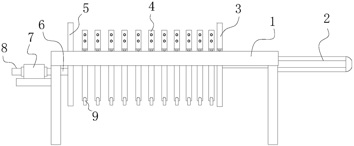
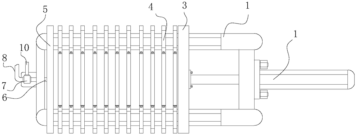
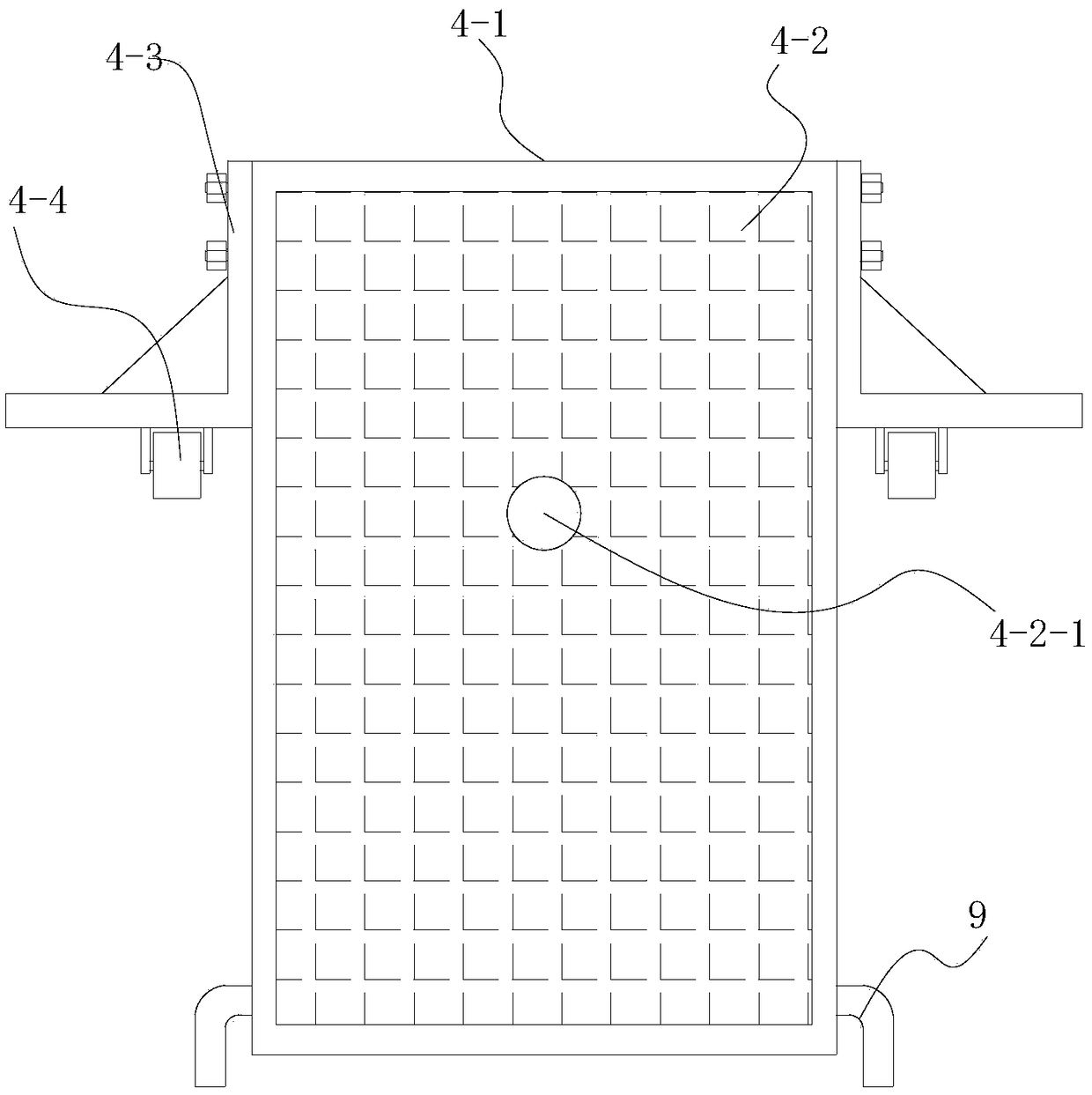
[0021] Such as Figure 1 to Figure 3 As shown, a metal powder dehydration device includes a lifting mechanism and a dehydration device arranged on the lifting mechanism. The lifting mechanism is composed of a support frame and two parallel guide rails 1 arranged on the support frame. The dehydration device is composed of a feeding mechanism, a loading mechanism and its linear drive assembly 2. The left end of the guide rail 1 is provided with a vertical constant pressure plate 5, and the positioning plate 5 can be welded on the guide rail 1. The right end of the guide rail 1 A vertical dynamic pressure plate 3 is provided, and the dynamic pressure plate 3 and the fixed pressure plate 5 are distributed parallel. The end part communicates with the discharge port of the ball mill at the far end, and a pressure pump is provided on the feeding pipe 8, the end of the booster air pipe 10 communicates with the external booster air pump, and the three-way valve 7 is installed on the le...

Embodiment 2

[0023] Such as Figure 1 to Figure 4 As shown, a metal powder dehydration device includes a lifting mechanism and a dehydration device arranged on the lifting mechanism. The lifting mechanism is composed of a support frame and two parallel guide rails 1 arranged on the support frame. The dehydration device is composed of a feeding mechanism, a loading mechanism and its linear drive assembly 2. The left end of the guide rail 1 is provided with a vertical constant pressure plate 5, and the positioning plate 5 can be welded on the guide rail 1. The right end of the guide rail 1 A vertical dynamic pressure plate 3 is provided, and the dynamic pressure plate 3 and the fixed pressure plate 5 are distributed parallel. The end part communicates with the discharge port of the ball mill at the far end, and a pressure pump is provided on the feeding pipe 8, the end of the booster air pipe 10 communicates with the external booster air pump, and the three-way valve 7 is installed on the le...


PUM


Abstract

The invention discloses a metal powder dehydration device, relating to the field of metal powder production equipment. The metal powder dehydration device comprises a lifting mechanism and a dehydration device arranged on the lifting mechanism, wherein the lifting mechanism comprises a support frame and two guide rails distributed on the support frame in parallel; the dehydration device comprisesa loading mechanism, a carrying mechanism and a linear driving assembly, a vertical fixed pressure plate is arranged at the left end of the guide rail, and a vertical movable pressure plate is arranged at the right end of the guide rail and is distributed in parallel with the fixed pressure plate; the loading mechanism comprises a three-way valve, a conveying pipe, a pressurizing gas pipe and an output pipe, the end part of the conveying pipe is communicated with a discharging hole of a distal ball mill, and the tail end of the pressurizing gas pipe is communicated with a pressurizing gas pumpoutside; and the carrying mechanism comprises a plurality of carrying assemblies which are distributed in parallel. The metal powder dehydration device is simple in structure, and the metal powder isdehydrated in a pressurization manner, so that the dehydration efficiency and the dehydration quality are improved, and the processing quality of the metal powder is improved.

Description

technical field [0001] The invention relates to the field of metal powder production equipment, in particular to a metal powder dehydration device. Background technique: [0002] The ball mill is the key equipment for crushing the material after it is crushed. A certain number of steel balls are installed in the cylinder as grinding media to grind metal objects. During the grinding process, relevant liquid is added to make the fluid containing metal powder after grinding, and then it is passed into the dehydration device for dehydration treatment. [0003] When dehydrating liquid metal powder, the equipment for preparing metal powder in the prior art has low dehydration efficiency and poor dehydration quality, so that the quality of the produced product is relatively poor. [0004] The Chinese patent application number 201220721928.5 discloses a metal powder dehydration device, including a dehydration device body, characterized in that an upper cover is provided on the top ...

Claims


Application Information

Patent Timeline
Patent Type & Authority Applications(China)
IPC IPC(8): B01D25/12B01D25/34B22F9/04
CPCB01D25/12B01D25/34B22F9/04B22F2009/043
Inventor 张世龙
Owner 芜湖市晨睿建材有限公司
Why Eureka
Eureka Blog
Learn More