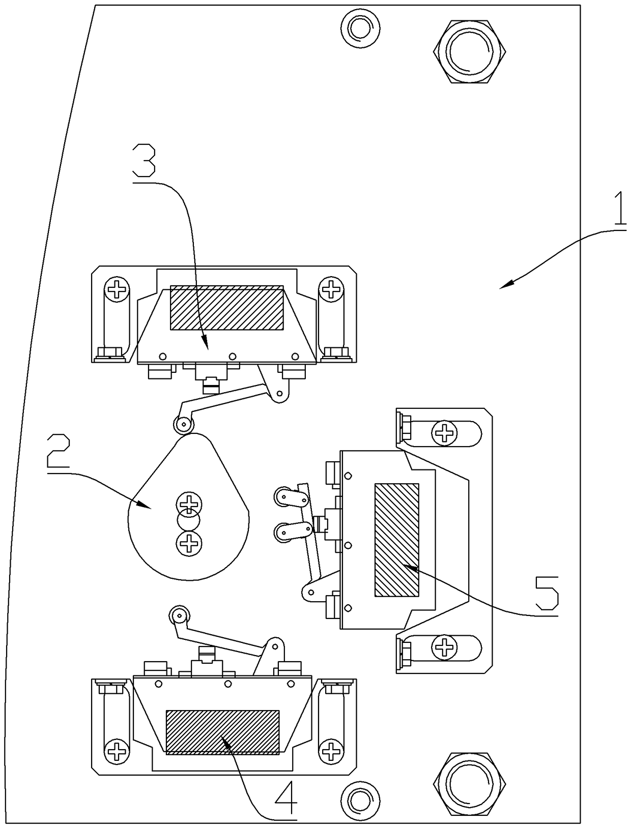
Three-station isolation switch and travel switch

A technology of isolating switch and travel switch, applied in the direction of air switch components, etc., can solve the problems of complex installation and debugging, low assembly efficiency, etc., to reduce the number of use, solve the complex installation and debugging, and simplify the logical relationship.

Pending Publication Date: 2018-12-04
HENAN SENYUAN ELECTRIC CO LTD
View PDF9 Cites 2 Cited by
  • Summary
  • Abstract
  • Description
  • Claims
  • Application Information

AI Technical Summary

Problems solved by technology

[0004] The purpose of the present invention is to provide a three-position isolating switch to solve the problems of complicated installation and debugging and low assembly efficiency of the current three-position isolating switch; in addition, the purpose of the present invention is to provide the above-mentioned three-position isolating switch The travel switch used

Method used


Image

  • Three-station isolation switch and travel switch
  • Three-station isolation switch and travel switch
  • Three-station isolation switch and travel switch

Examples


Embodiment 2

[0047] Specific embodiment 2 of the three-station isolating switch of the present invention, the difference between the structure of the three-station isolating switch in this embodiment and the structure of the above-mentioned three-station isolating switch is only: as Figure 12 and Figure 13 As shown, the signal rod 252 in this embodiment is provided with a two-way anti-sway member 253, and the swing stroke of the two-way anti-sway member 253 has a first anti-sway position and a second anti-sway position, and the cam 22 moves from the isolation closed position to the isolation position. In the opening position, the signal rod 252 is pressed by the two-way anti-swing member 253 in the first anti-swing position to trigger the opening travel switch, and when the cam 22 moves from the grounding closing position to the grounding opening position, it passes the two-way anti-swaying member in the first anti-swaying position. The rocker-stop member 253 presses the signal rod 252 t...


PUM


Abstract

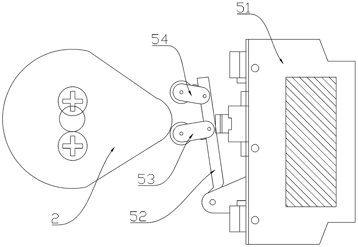
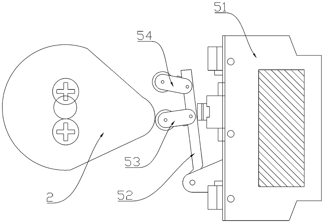
The invention relates to the switch equipment field and especially relates to a three-station isolation switch and a travel switch. The travel switch of the three-station isolation switch comprises aswitch body and a signal pole. The signal pole is hinged to first and second self-reset swing components. The first self-reset swing component has a first swing component stop position. The second self-reset swing component has a second swing component stop position. During usage, during isolation opening, a main shaft linkage component presses the signal pole through the first self-reset swing component located at the first swing component stop position to trigger the travel switch to trigger the travel switch. During grounding opening, through the second self-reset swing component located atthe second swing component stop position, the signal pole is pressed to trigger the travel switch. Whether the main shaft linkage component is in an isolation opening position or a grounding openingposition, the same travel switch can be triggered so that an opening signal is emitted, which reduces the number of magnetic blowout switches and simplifies the logic relationship of a circuit. By using an existing three-station isolation switch, installation and debugging are complex and assembling efficiency is low. In the invention, the above problems are solved.

Description

technical field [0001] The invention relates to the field of switchgear, in particular to a three-position isolating switch and a travel switch thereof. Background technique [0002] With the development of the power industry, more and more three-position disconnectors are used. The three-position isolating switch is often operated by electric control. The three-position isolating switch includes the isolating knife and the operating mechanism that drives the isolating knife. The operating mechanism includes the cam connected to the driving spindle and controls the operation according to the opening and closing position of the isolating knife. The travel switch of the mechanism and the cam form the main shaft linkage of the three-position isolating switch. The travel switch usually uses a magnetic blow switch. The magnetic blow switch includes a switch body and a movable rod hinged on the switch body. There is a pulley block on the movable rod. After the cam reaches the cor...

Claims


Application Information

Patent Timeline
Patent Type & Authority Applications(China)
IPC IPC(8): H01H31/10
CPCH01H31/10
Inventor 孙一帆程静厉复新袁丽丹赵睿哲
Owner HENAN SENYUAN ELECTRIC CO LTD
Why Eureka
Try Eureka