
Faucet handle and machining and electroplating method thereof

A faucet handle and handle technology, applied in the field of bathroom, can solve the problems of handle breakage, light weight of plastic handle, complicated process, etc., and achieve the effect of enhancing airtightness and airtightness, good airtightness and airtightness, and simple electroplating process.

Inactive Publication Date: 2018-12-04
XIAMEN LIYE IND & TRADE CO LTD
View PDF6 Cites 2 Cited by
  • Summary
  • Abstract
  • Description
  • Claims
  • Application Information

AI Technical Summary

Problems solved by technology

[0002] Existing faucet handles are generally made of metal materials, among which copper and zinc alloy are the majority. The cost of faucet handles made of copper and zinc alloy is relatively high, and the handle part of the zinc alloy faucet handle is prone to breakage after being used for a period of time. And the plastic handle is not as good as the metal handle because of its light weight.
[0003] In order to solve the above problems, the industry has produced a new faucet handle structure after research and improvement. The faucet handle structure mainly includes a handle shell, a counterweight and a fixed piece. The handle shell and the fixed piece are both injection molded. The fixed connection between the handle shell and the fixed piece encapsulates the counterweight in the accommodation space formed by the handle shell and the fixed piece. This structure solves the problem of the light weight of the plastic faucet handle. In order to make the plastic faucet handle also have metal Texture, it is often necessary to electroplate the handle of the faucet. At present, the electroplating process of the faucet handle is mainly divided into two methods. One is to electroplate the handle shell, and then install the counterweight on the handle shell. The fixed piece is fixedly connected with the handle shell. As a result, the handle shell which mainly plays a decorative role has electroplating, while the internal fixed piece has no electroplating. Although it can meet the needs of some customers, it cannot meet the needs of higher-end users. Customer demand
Second, the fixed plate and the counterweight are first encapsulated and molded, and then the handle shell is subjected to secondary overmolding, and finally the product is electroplated as a whole. Due to the complicated process and high cost of the faucet handle, and the inside of the finished product It will leave obvious traces of craftsmanship, that is, there will be traces of thimbles on the fixed piece inside the faucet handle due to the secondary overmolding
Therefore, neither of the two techniques can achieve a complete metallic texture.
For the first type of electroplating process, the industry has tried to assemble and process the handle shell, counterweight and fixed plate before performing overall electroplating. However, due to the limitations of the existing structure, it is impossible to make a connection between the handle shell and the fixed plate. To the seamless and non-porous connection, so that during the electroplating process, the electroplating solution will be immersed between the handle shell and the fixed piece, polluting the electroplating solution in the next process, resulting in the failure of the electroplating process

Method used


Image

  • Faucet handle and machining and electroplating method thereof
  • Faucet handle and machining and electroplating method thereof
  • Faucet handle and machining and electroplating method thereof

Examples


Embodiment Construction

[0024] The present invention will be further described below in conjunction with drawings and embodiments.

[0025] Such as Figure 1 to Figure 3 As shown, a faucet handle includes a handle housing 1 , a counterweight 2 and a fixing piece 3 .

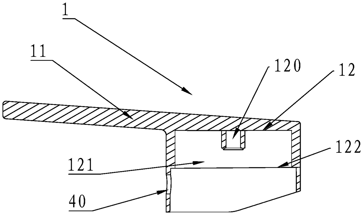
[0026] Wherein, the handle shell 1 and the fixing piece 3 are injection molded. The handle housing 1 is provided with an installation hole 10 , and the handle housing 1 includes a handle 11 and a faucet connecting portion 12 , and the faucet connecting portion 12 has a hollow accommodating portion 121 . A hollow column 120 is disposed at the center of the accommodating portion 121 , and an annular positioning step 122 is disposed on the inner wall of the accommodating portion 121 .

[0027] The counterweight 2 is disposed in the accommodating portion 121 , and the counterweight 2 is a cylinder, and a circular through hole 20 is formed in the center of the cylinder.

[0028] A square spool joint 4 is provided on the outside of the fix...


PUM


Abstract

The invention relates to a faucet handle. The faucet handle comprises a handle shell, a balance weight block and a fixed piece, wherein injection molding is adopted for the handle shell and the fixedpiece; the handle shell is provided with an installing hole, and comprises a handle and a faucet connection portion; the faucet connection portion is provided with a hollow containing portion; the balance weight block is arranged in the containing portion; a valve element connection head is arranged on the outer side of the fixed piece, and a positioning boss is arranged on the inner side; and thefixed piece is arranged in the containing portion on the outer side of the balance weight block and is welded to the handle shell in an interference manner. The faucet shell has the following beneficial effects that firstly, the structure is simplified, the electroplating process is simple, and cost is lower; secondly, the appearance face comprises a visible portion in the handle shell, and bothof them are very bright and clean, and the nearly perfect metal texture is achieved; thirdly, the fixed piece and the handle shell are in interference welding, so that gas tightness between the fixedpiece and the handle shell is better, and connection is more stable and reliable; and fourthly, the fixed piece is provided with an alignment groove, in the process of installing the fixed piece, thealignment groove is aligned with the installing hole, and the fixed piece can be accurately installed in place.

Description

technical field [0001] The invention relates to the field of sanitary ware, in particular to a faucet handle and a processing and electroplating method for the faucet handle. Background technique [0002] Existing faucet handles are generally made of metal materials, among which copper and zinc alloy are the majority. The cost of faucet handles made of copper and zinc alloy is relatively high, and the handle part of the zinc alloy faucet handle is prone to breakage after being used for a period of time. The plastic handle is not as good as the metal handle because of its light weight. [0003] In order to solve the above problems, the industry has produced a new faucet handle structure after research and improvement. The faucet handle structure mainly includes a handle shell, a counterweight and a fixed piece. The handle shell and the fixed piece are both injection molded. The fixed connection between the handle shell and the fixed piece encapsulates the counterweight in th...

Claims


Application Information

Patent Timeline
Patent Type & Authority Applications(China)
IPC IPC(8): F16K31/60B29C69/00
CPCB29C69/00F16K31/60
Inventor 李加庆
Owner XIAMEN LIYE IND & TRADE CO LTD
Learn More