
A safe water supply joint for motor vehicles and a water supply connection method

A connection method and technology of water joints, which are applied in the direction of hose connection devices, pipes/pipe joints/fittings, connections with fluid cut-off devices, etc., which can solve the problems of not having automatic opening and closing, safety accidents, and delays in water supply efficiency And other issues

Active Publication Date: 2020-05-05
成都海瑞斯轨道交通设备有限公司
View PDF6 Cites 1 Cited by
  • Summary
  • Abstract
  • Description
  • Claims
  • Application Information

AI Technical Summary

Problems solved by technology

[0006] The purpose of the present invention is to overcome the deficiencies of the prior art, to provide a safe water supply joint and a water supply connection method for motor vehicles, to solve the problem of working mistakes of the water supply personnel of the motor vehicle, forgetting to unplug the water inlet pipe in time after the completion of the water supply operation, and Problems leading to security incidents after startup
[0007] In addition, solve the problem that the water supply joints of the existing motor vehicles do not have the function of automatic opening and closing, so that workers need to open the valve switch after completing the water supply connection, which seriously delays the water supply efficiency

Method used


Image

  • A safe water supply joint for motor vehicles and a water supply connection method
  • A safe water supply joint for motor vehicles and a water supply connection method
  • A safe water supply joint for motor vehicles and a water supply connection method

Examples


Embodiment 1

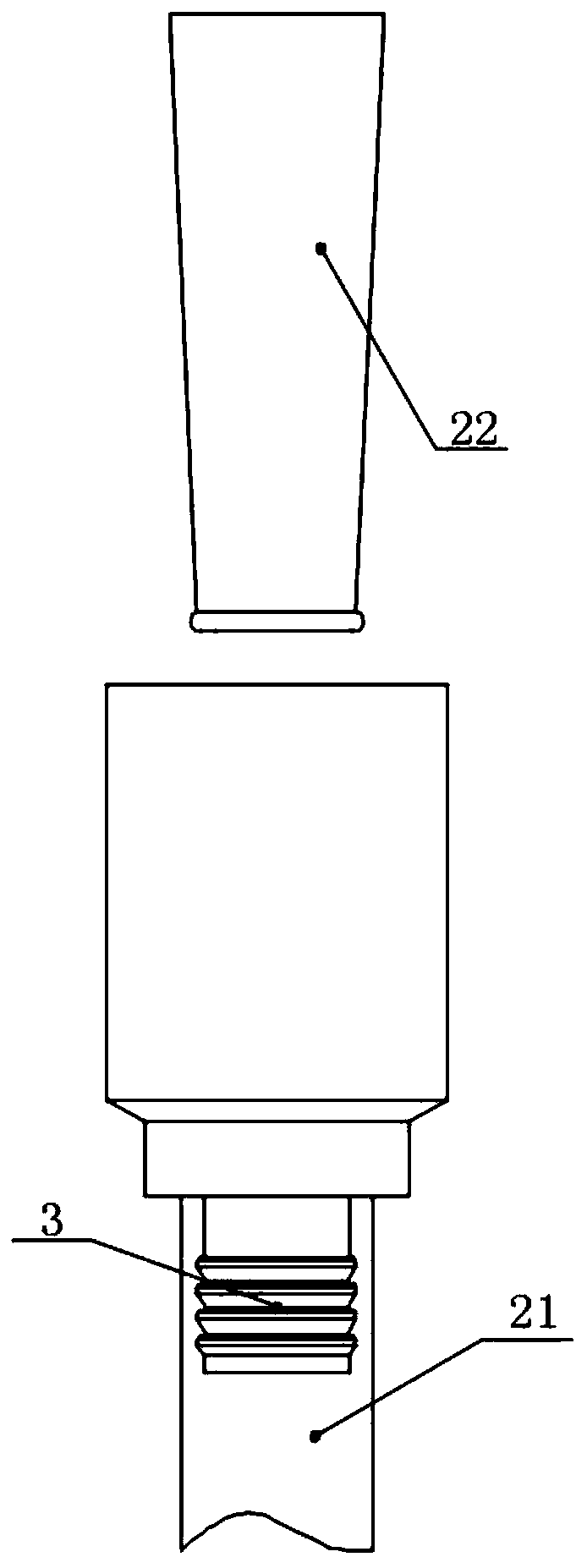
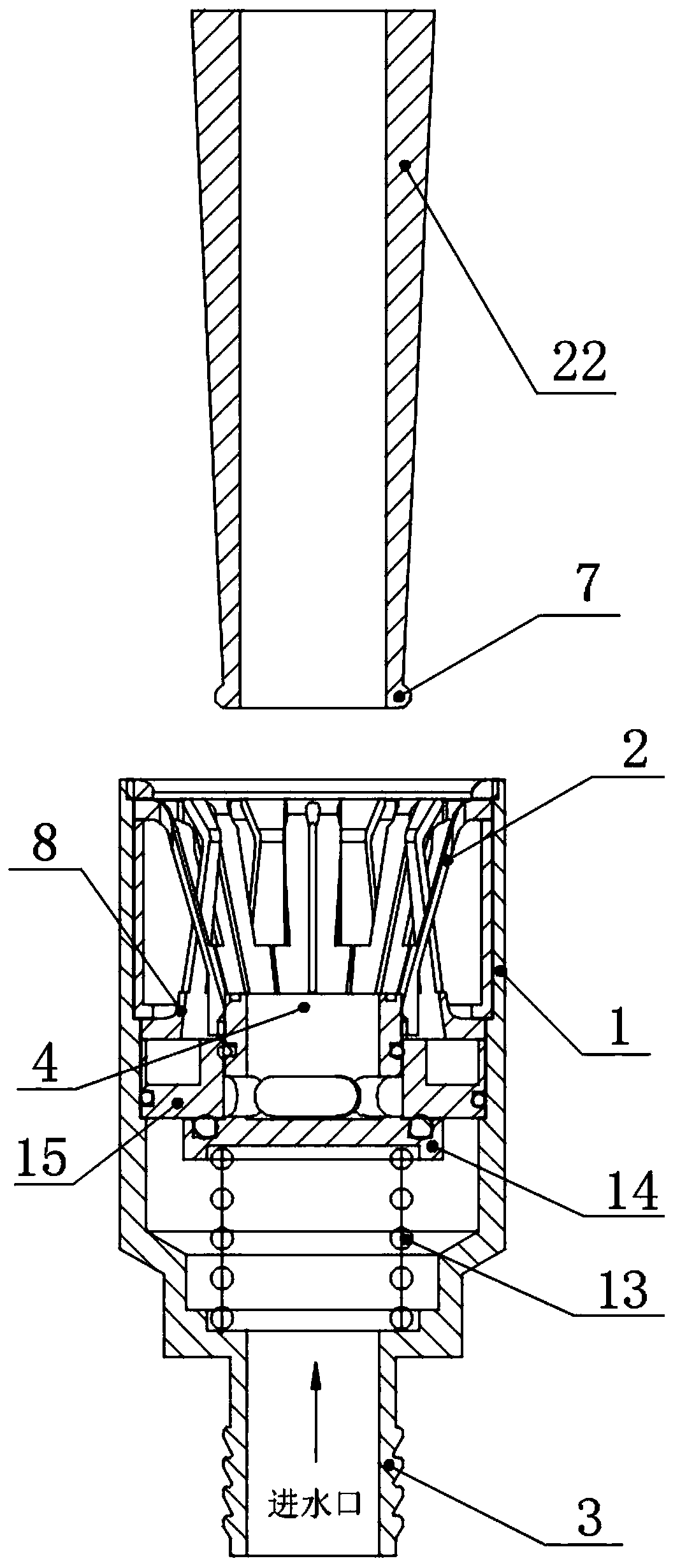
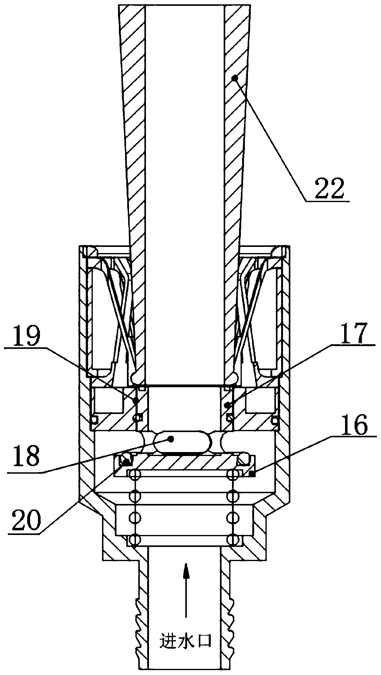
[0037] Such as Figure 1-5 As shown, a safety water supply joint for motor vehicles of the present invention includes a water supply joint housing 1, a check valve and a first water supply expansion ring 2, and the two ends of the water supply joint housing 1 are respectively large and small joints, and the big head is used to connect with the water supply joint. The connection end of the water supply joint 22, the small head is the water inlet pipe joint 3 for connecting with the water supply pipe 21, the lower end of the water supply joint housing 1 is provided with the water intake pipe joint 3, and the upper end of the water supply joint housing 1 is the installation cavity of the water supply joint 4. A check valve is provided at the lower part of the installation cavity 4 of the water supply joint; when the safe water supply joint and the water supply joint 22 are installed and connected, the check valve will be automatically triggered to open, and the water supply joint ...

Embodiment 2

[0045] Such as Figure 1-5 As shown, the present invention is a safe water supply joint for motor vehicles. On the basis of Embodiment 1, the check valve includes a check valve spring 13, a check valve seat 14 and a check valve sleeve 15, and the check valve spring 13 It is arranged at the bottom of the installation cavity 4 of the water supply joint. The check valve seat 14 includes a seat plate 16 and a check valve core barrel 17. The check valve core barrel 17 is arranged on the upper end surface of the seat plate 16. 17 and the seat plate 16 are surrounded by a water hole 18, and the bottom end surface of the seat plate 16 is set on the check valve spring 13; The middle part of the return valve sleeve 15 is provided with a check valve core installation hole 19 , and the check valve core barrel 17 of the check valve seat 14 is sealed and inserted in the check valve core installation hole 19 . The upper end surface of the seat plate 16 surrounds the check valve core barrel ...

Embodiment 3

[0048] Such as Figure 1-5 As shown, a water supply connection method for a motor vehicle safety water supply joint is characterized in that it includes the steps:

[0049] Step 1, use the water inlet pipe joint 3 to connect with the water inlet pipe 21, and open the water inlet pipe 21;

[0050] Step 2. Insert the water supply joint 22 into the first water supply expansion ring 2, and the water supply joint 22 is fixed on the bottom end of the water supply joint limit block 5 through the raised retaining ring 7 provided around its end, Thereby, the water supply joint 22 is tightly connected with the check valve, and the water supply joint clamping block 10 of the second water expansion ring 8 is clamped on the water supply joint, and the water supply joint 22 is squeezed by the check valve of the check valve at the same time. seat 14, so that the check valve core barrel 17 moves downward in the check valve core mounting hole 19, the seat plate 16 is separated from the check ...


PUM


Abstract

The invention discloses a bullet train safe water feeding connector and a water feeding connection method. The lower end of a water feeding connector shell is provided with a water inlet pipe connector, the upper end of the water feeding connector shell is a water feeding connector installation cavity, and the lower part of the water feeding connector installation cavity is provided with a check valve; a first water feeding expansion ring comprises a first water feeding expansion ring installation ring and a plurality of water feeding connector limiting blocks, the inner wall of the first water feeding expansion ring installation ring is wound with the upper ends of the multiple water feeding connector limiting blocks, the multiple water feeding connector limiting blocks are wound to forma frustum cylinder structure, the first water feeding expansion ring is mounted at the upper end of the interior of the water feeding connector installation cavity through the first water feeding expansion ring installation ring, when the water feeding connector is inserted into the first water feeding expansion ring, the water feeding connector is clamped and fixed to the bottom ends of the waterfeeding connector limiting blocks through a hump stopping ring arranged at the end head of the water feeding connector in a wound mode, accordingly the water feeding connector is in sealing connection with the check valve, and meanwhile, the water feeding connector makes the check valve be opened through extrusion. The bullet train water feeding connector ensures that a water feeding rubber pipeis not drawn away, and the potential safety hazards are decreased.

Description

technical field [0001] The invention relates to the technical field of safety water supply equipment on trains and motor vehicles, in particular to a safety water supply joint and a water supply connection method for motor vehicles. Background technique [0002] At present, during the operation of the train, in order to meet the water demand of the train, the water supply equipment is arranged along the line to arrange the water supply for the train. However, bullet trains usually stop at stations for a short period of time, so safety accidents in which multiple motor vehicles towed away the water rubber hoses have occurred at many railway stations across the country, and even caused personal injury and death accidents. According to the analysis of the accidents that have occurred, the main reasons are as follows: [0003] (1) The water supply personnel of the EMU made mistakes in their work and forgot to unplug the water inlet pipe in time after the water supply operation ...

Claims


Application Information

Patent Timeline
Patent Type & Authority Patents(China)
IPC IPC(8): F16L33/025F16L29/02B61K11/00
CPCB61K11/00F16L29/02F16L33/025
Inventor 冯德祥刘良张博贾兵程卓
Owner 成都海瑞斯轨道交通设备有限公司
Learn More