
Four-bottom three-cavity injector

An injector, integrated technology, applied in jet propulsion devices, machines/engines, rocket engine devices, etc., can solve the problems of efficient combustion in the combustion chamber, difficulty in greatly varying thrust and stable combustion, and increased propellant flow. Combustion instability, reducing fluid velocity, avoiding the effect of uneven flow field

Active Publication Date: 2018-11-30
BEIJING AEROSPACE PROPULSION INST
View PDF8 Cites 10 Cited by
  • Summary
  • Abstract
  • Description
  • Claims
  • Application Information

AI Technical Summary

Problems solved by technology

[0004] A single high-thrust high-pressure afterburning cycle engine has a single thrust of hundreds of tons, and the propellant flow rate in the combustion chamber has increased significantly, making efficient combustion in the combustion chamber, large thrust change and stable combustion more difficult

Method used


Image

  • Four-bottom three-cavity injector
  • Four-bottom three-cavity injector
  • Four-bottom three-cavity injector

Examples


Embodiment Construction

[0036] The present invention will be described in detail below in conjunction with the accompanying drawings and examples.

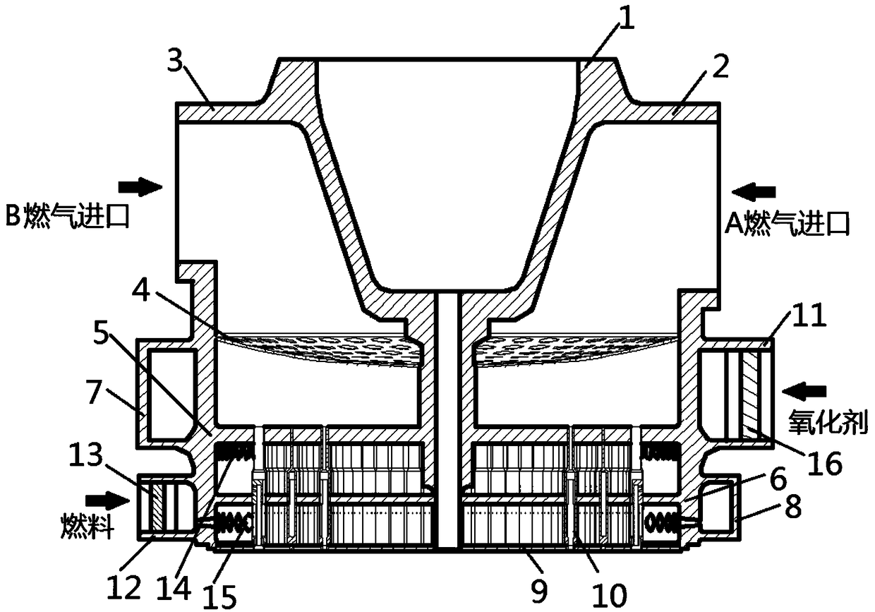
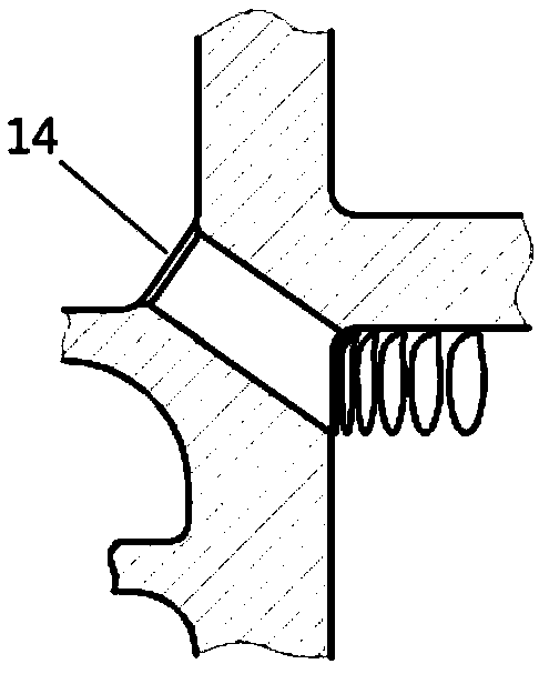
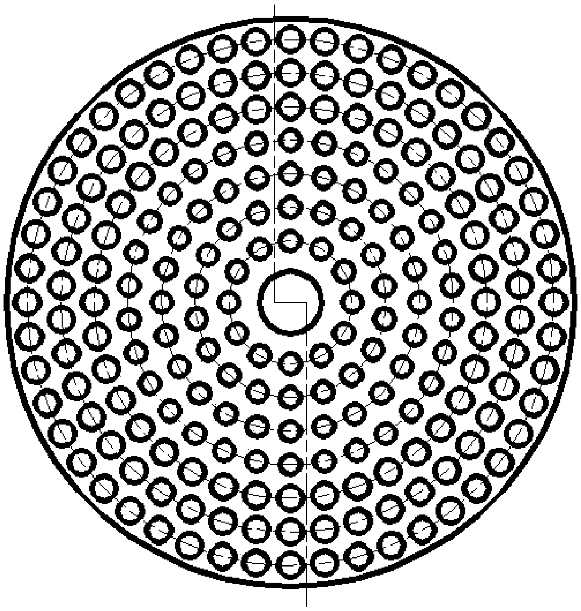
[0037] Such as figure 1 As shown, a four-bottom three-chamber injector includes a bearing seat and a gas roof integrated part 1, A gas inlet section 2, B gas inlet section 3, porous gas rectifying grid 4, three bottoms with rings and a fire guide Pipe body 5 , second bottom 6 with ring, oxidant collector 7 , fuel collector 8 , first bottom 9 , nozzle assembly 10 , oxidant inlet section 11 , and fuel inlet section 12 .

[0038] The integrated part 1 of the load bearing seat and the gas top cover, the porous gas rectifying grid 4, and the integrated part 5 of the three bottoms with rings and the fire guide tube together constitute the gas head chamber; the A gas inlet section 2 and the B gas inlet section 3 are distributed at 180° At both ends of the gas head cavity, and respectively the inlets of B gas and A gas; the porous gas rectifying grid 4 is distr...


PUM


Abstract

Provided is a four-bottom three-cavity injector. A bearing seat and gas top cover integrated piece and a belt ring three-bottom and fuze integrated piece form a gas chamber; a chamber jointly definedby the belt ring three-bottom and fuze integrated piece and a belt ring two-bottom jointly is an oxidant chamber, an oxidant inlet section is an inlet of an oxidant and is communicated with an oxidantcollector, and the oxidant inlet section is provided with a flow deflector that divides an incoming flow oxidant into two strands that flow into the two sides of the oxidant collector respectively. Achamber defined by a belt ring two-bottom and a one-bottom is a fuel chamber, a fuel inlet section is a fuel inlet and is communicated with a fuel collector, and the fuel inlet section is provided with a flow deflector that divides incoming flow fuel into two strands that flow into the two sides of the fuel collector respectively; and nozzle assemblies are mounted on the belt ring three-bottom and fuze integrated piece, the belt ring two-bottom and the one-bottom. The gas chamber, the oxidant chamber and the fuel chamber are sequentially distributed from top to bottom.

Description

technical field [0001] The invention relates to a four-bottom three-chamber injector, which can be used in the fields of aerospace, thermal energy engineering and combustion technology. Background technique [0002] The high-pressure afterburning cycle engine has a series of advantages such as large thrust and high specific impulse, and is the preferred power for the upper stage of heavy-duty launch vehicles for manned moon landings and deep space exploration in the future. The United States, the former Soviet Union (Russia), Japan and other space powers have successively developed the SSME, RD-0120, and LE-7 series of 100-ton high-thrust supplementary combustion engines. The thrust of the engines is between 100 and 300 tons. The core-level power system has advantageously improved the rocket's carrying capacity. [0003] The thrust of a single high-thrust high-pressure afterburning cycle engine is on the order of hundreds of tons, and the size of the combustion chamber is s...

Claims


Application Information

Patent Timeline
Patent Type & Authority Applications(China)
IPC IPC(8): F02K9/52F02K9/60
CPCF02K9/52F02K9/60
Inventor 刘倩丁兆波潘亮王洋洲刘红珍张晋博孔维鹏潘刚左安军卢明许晓勇孙纪国郑孟伟
Owner BEIJING AEROSPACE PROPULSION INST
Learn More