
Label removal device of plastic bottle

A technology for plastic bottles and labels, which is applied in the directions of cleaning hollow objects, cleaning methods and utensils, chemical instruments and methods, etc., can solve the problems of low efficiency, time-consuming and labor-intensive label removal methods, and achieves reasonable and novel design, convenient operation and simple structure. Effect

Inactive Publication Date: 2018-11-30
唐师正
View PDF7 Cites 12 Cited by
  • Summary
  • Abstract
  • Description
  • Claims
  • Application Information

AI Technical Summary

Problems solved by technology

[0002] At present, portable beverages such as bottled mineral water are more and more popular due to their portability, cleanliness and hygiene, followed by the production of a large number of discarded plastic bottles, and plastic bottles have good recycling value, but the disposal Previously, it was necessary to remove the labels attached to the bottle body, but the currently used label removal methods are inefficient, time-consuming and labor-intensive

Method used


Image

  • Label removal device of plastic bottle
  • Label removal device of plastic bottle
  • Label removal device of plastic bottle

Examples


Embodiment 1

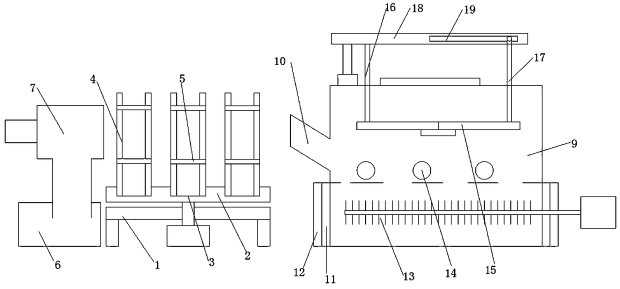
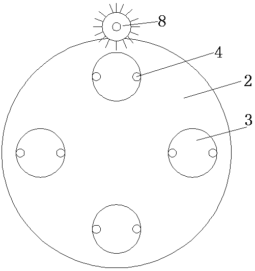
[0016] Such as Figure 1-3 As shown, the present invention is a plastic bottle label removal device, including a support base 1, a rotating base 2 driven by a motor is arranged above the supporting base 1, and several grooves 3 are arranged on the rotating base 2 , preferably, the number of grooves is four, which are symmetrically arranged in pairs, and support frames 4 are also provided on the left and right sides above each of the grooves 3, and limit stops are respectively set above and below the two support frames 4 Circle 5, the plastic bottle is placed in the support frame and is limited by the limit circle, and the position of the label is leaked. On the rear side of the rotating base 2, there is also a needle roller 8 driven by a motor to rotate. In the process of rotation, it contacts with the label of the plastic bottle to achieve the purpose of piercing the label. The rotation speed of the needle roller is greater than that of the rotating base. In this way, the nee...

Embodiment 2

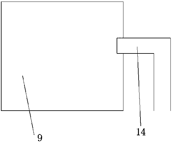
[0018] Such as Figure 4 As shown, the present invention is a plastic bottle label removal device, comprising a support base 1, a rotating base 2 driven by a motor is arranged above the supporting base 1, and several Groove 3, preferably, the number of grooves is four, symmetrically arranged in pairs, support frames 4 are also arranged on the left and right sides above each of the grooves 3, and above and below the two support frames 4 respectively Set the limit ring 5, place the plastic bottle in the support frame and limit the position through the limit ring, and leak the position of the label. On the rear side of the rotating base 2, there is also a needle roller 8 driven by a motor to rotate on the needle roller The piercing needles are in contact with the label of the plastic bottle during the rotation, which can achieve the purpose of piercing the label. The rotation speed of the needle roller is greater than the rotation speed of the rotating base. In this way, the need...


PUM


Abstract

The invention relates to a label removal device of a plastic bottle. The label removal device comprises a support base, wherein a rotary base is arranged above the support base and is driven by a motor to rotate; the rotary base is provided with a plurality of grooves; support frames are arranged at the left side and right side of the upper part of each groove; limiting rings are respectively arranged above and under the two support frames; a puncturing needle roll is arranged at the back side of the rotary base and is driven by a motor to rotate; an air pipe is arranged at one side of the rotary base and is connected with a fan; the fan is connected with a label collecting cylinder; a cleaning cylinder is arranged at one side of the rotary base; one side of the cleaning cylinder is provided with an inclined feeding port; overflow pipes are arranged at the back end of the cleaning cylinder and the lower end of the inclined feeding port; a brush roll is arranged in the cleaning cylinder, and is driven by a motor to rotate; two press plates with leaking holes are arranged in the cleaning cylinder. The label removal device can effectively complete the removal of the labels of plasticbottles, especially mineral water bottles.

Description

technical field [0001] The invention belongs to a resource recovery and reuse device, in particular to a plastic bottle label removal device. Background technique [0002] At present, portable beverages such as bottled mineral water are more and more popular due to their portability, cleanliness and hygiene, followed by the production of a large number of discarded plastic bottles, and plastic bottles have good recycling value, but the disposal Previously, it was necessary to remove the labels adhered to the bottle, but the currently used label removal methods are inefficient, time-consuming and labor-intensive. Contents of the invention [0003] In order to solve the above problems, the present invention provides a plastic bottle label removal device, which can effectively remove the labels and has high processing efficiency. [0004] In order to achieve the above object, the present invention is achieved through the following technical solutions: [0005] The present i...

Claims


Application Information

Patent Timeline
IPC IPC(8): B08B9/08B08B9/36
CPCB08B9/083B08B9/36
Inventor 唐师正
Owner 唐师正
Learn More