
A hot melt glue injection valve

A technology of hot melt adhesive and jet valve, which is applied to the devices and coatings for coating liquid on the surface, can solve the problems such as the inability to accurately adjust the injection amount, the injection is not uniform enough, and the glue dispensing cannot be realized, so as to achieve long service life, The effect of uniform spray and fine dispensing

Active Publication Date: 2020-10-02
VISION XIAMEN AUTOMATION TECH CO LTD
View PDF6 Cites 2 Cited by
  • Summary
  • Abstract
  • Description
  • Claims
  • Application Information

AI Technical Summary

Problems solved by technology

This kind of injection valve has the following disadvantages: the injection speed is slow, the injection is not uniform enough, the minimum injection volume is too large, it is impossible to achieve finer and more precise dispensing, and the injection volume cannot be adjusted precisely
Existing injection valves cannot meet this requirement

Method used


Image

  • A hot melt glue injection valve
  • A hot melt glue injection valve
  • A hot melt glue injection valve

Examples


Embodiment Construction

[0024] The present invention will now be further described with reference to the accompanying drawings and specific embodiments.

[0025] In the description of the present invention, it should be understood that the terms "upper", "lower", "vertical", "horizontal", "top", "bottom", "inner", "outer" and the like indicate orientation or The positional relationship is based on the orientation or positional relationship shown in the accompanying drawings, which is only for the convenience of describing the present invention and simplifying the description, rather than indicating or implying that the referred device or element must have a specific orientation, be constructed and operated in a specific orientation, Therefore, it should not be construed as a limitation of the present invention.

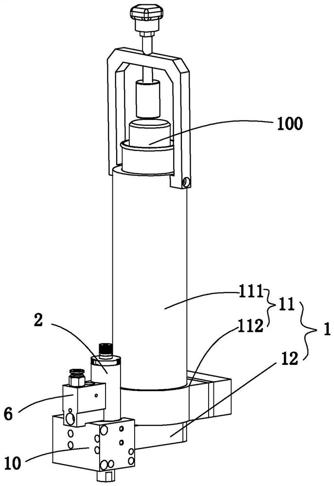
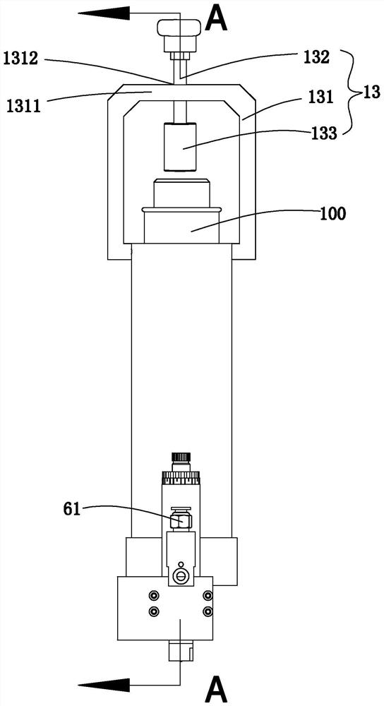
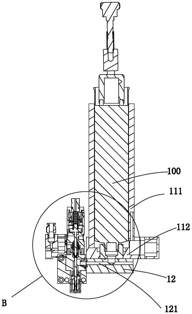
[0026] like Figure 1-4 As shown, a hot melt adhesive injection valve may include a hot melt adhesive heating device 1 , a valve body 2 , a valve core 3 and a striker 4 . The hot melt adhe...


PUM


Abstract

The invention relates to a hot melt adhesive spray valve. The hot melt adhesive spray valve can comprise a hot melt adhesive heating device, a valve body, a valve element and a striker. Heat transferof the hot melt adhesive heating device acts on a hot melt adhesive tank and a flow channel, wherein the flow channel communicates with an outlet of the hot melt adhesive tank. The valve body comprises a first cavity and a second cavity, wherein the first cavity and the second cavity are spaced from each other in a sealed manner. The first cavity is provided with an air inlet. On and off switchingof an air inlet channel communicating with the air inlet is achieved through a high-frequency air inlet and outlet switch. The air inlet end of the high-frequency air inlet and outlet switch is connected with high-pressure air. The second cavity is provided with an adhesive inlet and a spray orifice, wherein the adhesive inlet communicates with the flow channel, and the spray orifice is formed inthe lower end. The valve element is jointed into the first cavity in a sealed manner and connected with an elastic component. The upper end of the striker is fixed to the valve element and extends tothe second cavity. The lower end of the striker can plug the spray orifice. The valve element can perform reciprocation motion in the first cavity under the effect of the high-pressure air and the elastic component, and furthermore, the striker is driven to perform reciprocating motion so that hot melt adhesive entering the second cavity through the flow channel can be sprayed out of the spray orifice.

Description

technical field [0001] The invention relates to a hot melt glue injection valve. Background technique [0002] Hot melt adhesive is a kind of plastic adhesive. Its physical state changes with the change of temperature within a certain temperature range, but its chemical properties remain unchanged. It is non-toxic and tasteless, and is an environmentally friendly chemical product. Because the product itself is solid, it is easy to package, transport, store, solvent-free, pollution-free, non-toxic; as well as simple production process, high added value, high bonding strength, fast speed and other advantages. [0003] In the automatic dispensing industry, the injection valve is a more critical component. The quality of the injection valve injection greatly affects the automatic dispensing effect and even determines whether automatic dispensing can be achieved. Most of the existing injection valves used for dispensing glue are to lift the needle to open the nozzle of the injec...

Claims


Application Information

Patent Timeline
Patent Type & Authority Patents(China)
IPC IPC(8): B05C5/02B05C5/00
CPCB05C5/001B05C5/0237
Inventor 黄清耀
Owner VISION XIAMEN AUTOMATION TECH CO LTD
Learn More