Periscopic type panoramic image imaging device and system

A technology of panoramic image and imaging device, applied in image communication, TV system components, TV and other directions, can solve the problems of many lenses, inconvenient to carry, small size, etc., to achieve multi-view information, large field of view pitch angle, wide field of view The effect of pitch angle

Inactive Publication Date: 2018-11-27
陈俊瑞
View PDF11 Cites 5 Cited by
  • Summary
  • Abstract
  • Description
  • Claims
  • Application Information

AI Technical Summary

Problems solved by technology

The existing panoramic optical system imaging methods are divided into two types: single-lens fixed-point multi-angle imaging and multi-lens array imaging. The single-lens fixed-point multi-angle imaging is small in size and low in cost, and has a certain market. The disadvantage is that it cannot be moved Real-time shooting of photos in various directions requires fixed-point shooting before splicing, so it cannot achieve a real-time panoramic system with a 360-degree field of view without dead ends.
Multi-lens array imaging is a panoramic system that uses multiple ordinary limited field of view lenses to stitch together a panoramic system. The system can achieve a 360-degree full viewing angle, and the system uses ordinary lenses, so the cost is not high. The disadvantage is that it requires many lenses, which are bulky and inconvenient to carry. , the photos taken also need to be processed and stitched, and the maintenance cost is high

Method used


Image

  • Periscopic type panoramic image imaging device and system

Examples


Embodiment Construction

[0022] The present invention will be further elaborated below in conjunction with the accompanying drawings and specific embodiments.

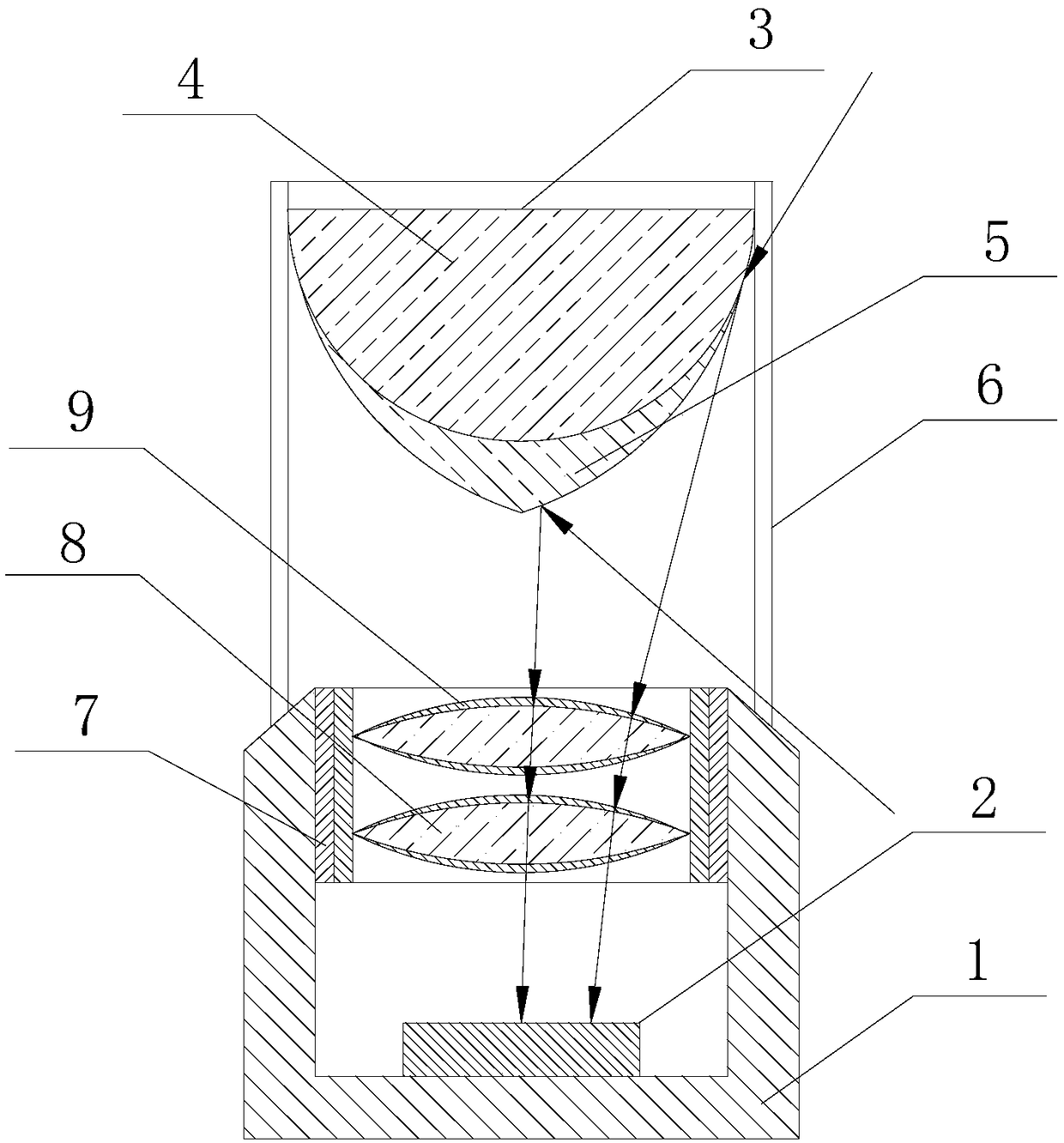
[0023] like figure 1 As shown, this embodiment provides a periscope panoramic image imaging device, including a cylinder body 1, which is provided with a photosensitive element 2 for receiving light signals reflected from the object to be photographed, and a cylinder body 1 is also provided with There is a lens assembly for projecting the light signal of the object to be photographed on the photosensitive element 2 .

[0024] The barrel 1 has a certain thickness, the bottom of the barrel 1 is generally closed, the photosensitive element 2 is set at the bottom of the barrel 1, the lens assembly is set at the top of the barrel 1, and the optical signal of the object to be photographed passes through the lens assembly and is projected on the On the photosensitive element 2, the photosensitive element 2 converts all light signals into electrical ...


PUM


Abstract

The invention belongs to the technical field of lens imaging and discloses a periscopic type panoramic image imaging device and system. The periscopic type panoramic image imaging device comprises a barrel body, wherein the barrel body is internally provided with a light-sensing element for receiving a light signal reflected by a photographed object; the barrel body is internally further providedwith a camera lens assembly which is used for projecting the light signal of the photographed object to the light-sensing element; a semi-oval-shaped reflection mirror for reflecting the light signalof the photographed object at the periphery into the camera lens assembly is arranged above the barrel body; the bottom of the reflection mirror is of a sharp end shape. According to the periscopic type panoramic image imaging device and system, 360-degree panoramic information at the periphery can be obtained by adopting the reflection mirror, and the bottom of the reflection mirror is of the sharp end shape, so that a relatively wide view-field pitch angle can be obtained and the device has a 360-degree panoramic photographing function; meanwhile the periscopic type panoramic image imaging device has the relatively wide view-field pitch angle and meets special utilization requirements.

Description

technical field [0001] The invention belongs to the technical field of lens imaging, and in particular relates to a periscope panoramic image imaging device and system. Background technique [0002] With the continuous advancement of industrial technology, panoramic optical systems have been widely used in security, robot vision, navigation and military applications. The existing panoramic optical system imaging methods are divided into two types: single-lens fixed-point multi-angle imaging and multi-lens array imaging. The single-lens fixed-point multi-angle imaging is small in size and low in cost, and has a certain market. The disadvantage is that it cannot be moved Real-time shooting of photos in various directions requires fixed-point shooting before splicing, so it cannot achieve a real-time panoramic system with a 360-degree field of view without dead angles in the true sense. Multi-lens array imaging is a panoramic system that uses multiple ordinary limited field of...

Claims


Application Information

Patent Timeline
Patent Type & Authority Applications(China)
IPC IPC(8): H04N5/225
CPCH04N23/51H04N23/54H04N23/50
Inventor 陈俊瑞
Owner 陈俊瑞
Why Eureka
Try Eureka