Low-NOx sintering system based on double-layer ignition of double-layer cloth

A cloth and double-layer technology, applied in the field of low NOx sintering system, can solve the problems of long flue gas treatment process route, difficult disposal, and increased denitrification cost, so as to meet the requirements of ensuring sintering efficiency and catalyst, and is conducive to environmental protection. The effect of saving denitrification cost

Inactive Publication Date: 2018-11-27
武汉钢铁有限公司 +1
View PDF6 Cites 2 Cited by
  • Summary
  • Abstract
  • Description
  • Claims
  • Application Information

AI Technical Summary

Problems solved by technology

However, most low-temperature denitrification catalysts are noble metals, which are expensive and prone to oxygen inhibition and sulfur poisoning.
[0003] Most of the existing sintering flue gas pollutant treatment processes focus on the combination of single technical units for single pollutant treatment, which leads to long routes, large floor space, complex process control, large investment, and operating costs in the flue gas treatment process. A series of high-level problems have brought huge cost pressures to iron and steel enterprises
Especially when the SCR denitrification technology, which is generally accepted at present, is applied in the treatment of sintering flue gas, because sulfur will cause catalyst poisoning, the SCR denitrification system is generally installed after the desulfurization system, resulting in a further decrease in flue gas temperature, which is much lower than the SCR denitrification temperature window
Therefore, in the current sintering flue gas SCR denitrification project case, additional energy needs to be provided to raise the temperature of the flue gas to reach the SCR denitrification temperature window, which increases the cost of denitrification
At the same time, the SCR denitrification catalyst contains precious metals, the manufacturing cost is high, and it is difficult to dispose after failure

Method used


Image

  • Low-NOx sintering system based on double-layer ignition of double-layer cloth

Examples


Embodiment 1

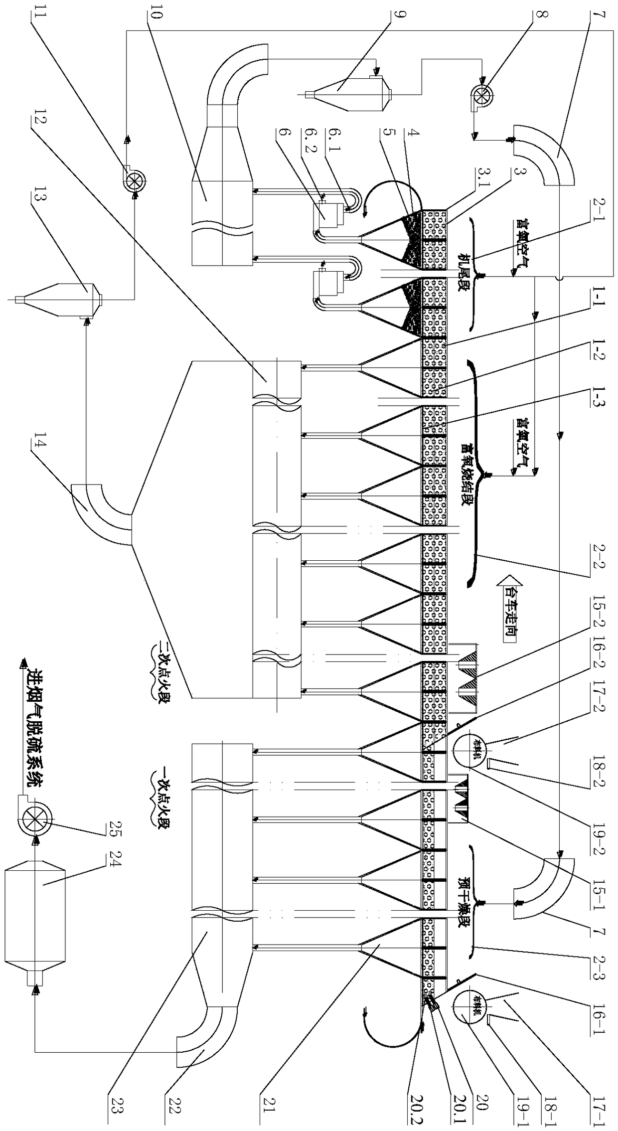
[0034] Example 1, see figure 1 , a low-NO x The sintering system includes a sintering machine 3, the sintering base material 1-3 is arranged on the sintering machine 3, and the bellows 21 is arranged under the trolley 3.1 of the sintering machine 3. Along the traveling direction of the trolley, the sintering machine 3 is sequentially divided into a lower sintering mixture distribution section, a pre-drying section, a primary ignition section, an upper sintering mixture distribution section, a secondary ignition section, an oxygen-enriched sintering section, and a tail section. Above the lower floor sintering mixture distribution section, be provided with the lower floor sintering mixture distribution machine 19-1 for laying the lower floor sintering mixture 1-2 on the sintering machine 3, and the lower floor sintering mixture distribution machine 19-1 is connected with the lower floor sintering mixture respectively. The lower hopper 17-1, the lower layer sintering mixture fee...

Embodiment 2

[0046] Embodiment 2, a kind of low NO based on double-layer cloth double-layer ignition x The sintering system includes a sintering machine, which is equipped with a sintering bottom material, and a bellows is installed under the trolley of the sintering machine, and the bellows discharges the flue gas; along the traveling direction of the trolley, the sintering machine is divided into the lower sintering mixture distribution section, the primary Ignition section, upper layer sintering mixture distribution section, secondary ignition section, oxygen-enriched sintering section, machine tail section; above the lower layer sintering mixture distribution section, there is a lower layer sintering mixture distribution machine for laying the lower layer sintering mixture on the sintering machine , the lower layer sintered mixture distribution machine is respectively connected with the lower layer sintered mixture discharge hopper, the lower layer sintered mixture discharge gate, and t...

Embodiment 3

[0047] Example 3 is different from Example 2 in that several sintering mixture distribution sections and ignition sections are provided between the secondary ignition section and the oxygen-enriched sintering section, and one sintering mixture distribution section corresponds to one ignition section.

[0048] The invention has the advantages of simple system, energy saving and environmental protection, saving investment cost of pollutant treatment, and can effectively reduce NO in the sintering process. x , Dioxin and dust emission concentration characteristics.


PUM

PropertyMeasurementUnit
diameteraaaaaaaaaa
thicknessaaaaaaaaaa
diameteraaaaaaaaaa

Abstract

The invention discloses a low-NOx sintering system based on double-layer ignition of double-layer cloth. The system comprises a sintering machine, and an air bellow is arranged on the lower portion ofeach trolley of the sintering machine; in the advance direction of the trolleys, the sintering machine is sequentially divided into a lower layer sintering mixture cloth segment primary ignition segment, an upper layer sintering mixture cloth segment, a secondary ignition segment, an oxygen-enriched sintering segment and a machine tail segment; a lower layer sintering mixture cloth machine is arranged above the lower layer sintering mixture cloth segment; an upper layer sintering mixture cloth machine is arranged above the upper layer sintering mixture cloth segment; a lower layer sintering mixture ignition system is arranged on the primary ignition segment; an upper layer sintering mixture ignition system is arranged on the secondary ignition segment. The two sets of sintering mixture cloth machines and the two sets of ignition systems are adopted, in this way, generation of NOx is reduced from the source, and the cost for abating smoke pollutants is lowered; the thickness of a sintering material layer is increased, and accordingly the amount of sintering ore is increased.

Description

technical field [0001] The invention belongs to the technical field of metallurgy energy saving and environmental protection, and in particular relates to a low NO x Sintering system. Background technique [0002] The selective catalytic reduction method has a high denitrification efficiency and has been widely used in coal-fired flue gas NO in thermal power plants. x removal. However, the one-time investment cost of the SCR flue gas denitrification technology in the selective catalytic reduction method is high (the catalyst cost accounts for 30-40% of the total investment cost), and the existing SCR flue gas denitrification technology is generally carried out at 350-450 °C , it needs to consume a lot of heat energy to heat the flue gas after desulfurization, which additionally increases the operating cost of SCR denitrification. In order to save energy consumption, many researchers have carried out research work on low-temperature catalysts. However, most low-temperatur...

Claims


Application Information

Patent Timeline
Patent Type & Authority Applications(China)
IPC IPC(8): F27B21/00F27B21/10F27B21/08F27D17/00
CPCF27B21/00F27D3/0084F27D17/004F27M2003/04
Inventor 吴高明陈铁军许丽娟付本全周仙霖
Owner 武汉钢铁有限公司
Why Eureka
Try Eureka