
A constant pressure control system and method for chemical grouting pump

A chemical grouting, constant pressure control technology, applied in pump control, pump testing, liquid variable capacity machinery, etc., can solve the problems of unsafe operation, poor dynamic performance of chemical grouting pump pressure regulation, low stability, etc. Accurate pressure control, guaranteed pressure stability, and strong adaptability

Pending Publication Date: 2018-11-27
WUHAN CHANGJIANG KECHUANG TECH DEV +1
View PDF5 Cites 1 Cited by
  • Summary
  • Abstract
  • Description
  • Claims
  • Application Information

AI Technical Summary

Problems solved by technology

[0003] The purpose of the present invention is to overcome the above-mentioned technical deficiencies, provide a chemical grouting pump constant pressure control system and method, and solve the technical problems of poor pressure regulation dynamic performance, low stability and unsafe operation of chemical grouting pumps in the prior art

Method used


Image

  • A constant pressure control system and method for chemical grouting pump
  • A constant pressure control system and method for chemical grouting pump
  • A constant pressure control system and method for chemical grouting pump

Examples


Embodiment 1

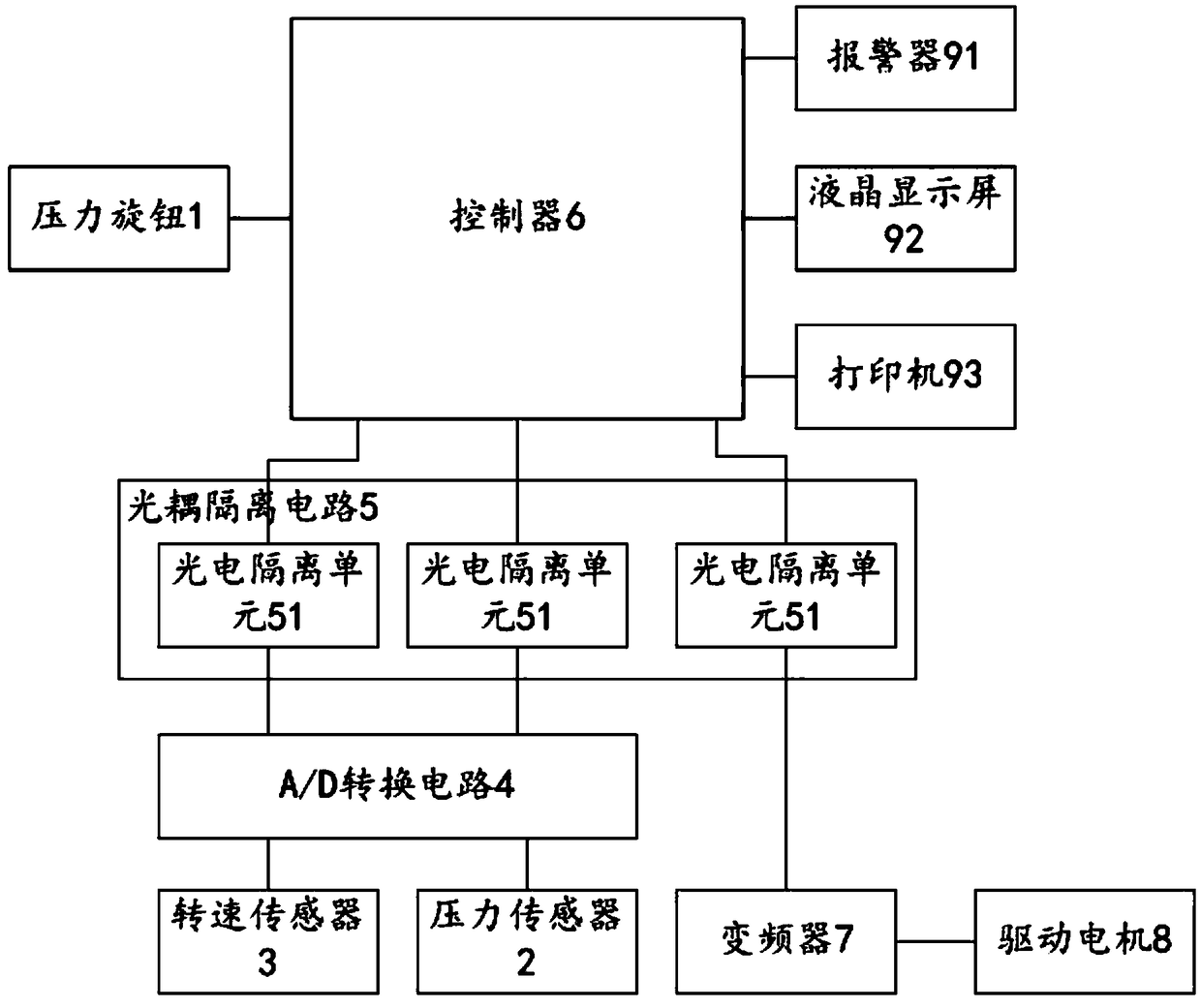
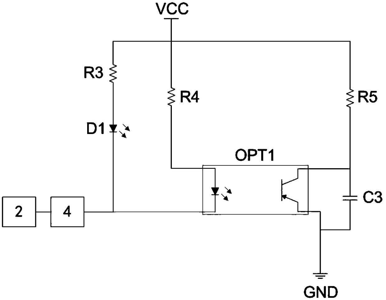
[0026] Such as figure 1 As shown, Embodiment 1 of the present invention provides a chemical grouting pump constant pressure control system, hereinafter referred to as the constant pressure control system, including a pressure knob 1, a pressure sensor 2, a speed sensor 3, an A / D conversion circuit 4, an optocoupler An isolation circuit 5, a controller 6, a frequency converter 7, and a drive motor 8, the pressure knob 1 is electrically connected to the controller 6, and the pressure sensor 2 and the rotational speed sensor 3 are connected to each other through the A / D conversion circuit 4 and The optocoupler isolation circuit 5 is electrically connected, the optocoupler isolation circuit 5 is electrically connected to the controller 6, and the controller 6 is also electrically connected to the frequency converter 7 through the optocoupler isolation circuit 5, so The driving motor 8 is electrically connected to an external power supply through the frequency converter 7, the pres...

Embodiment 2

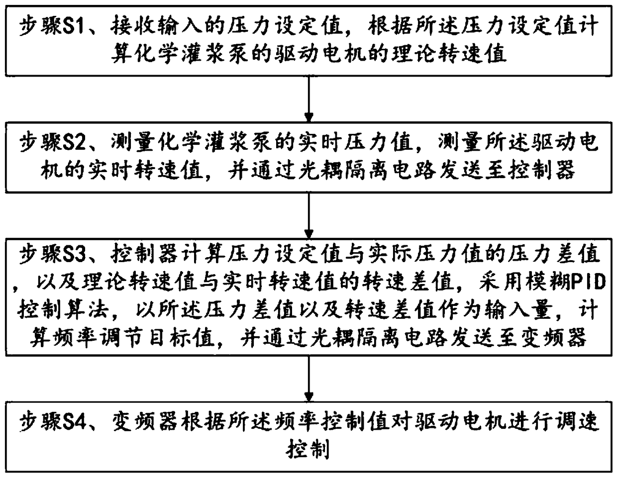
[0054] Such as image 3 As shown, Embodiment 2 of the present invention provides a method for controlling constant pressure of a chemical grouting pump, comprising the following steps:

[0055] Step S1, receiving the input pressure setting value, and calculating the theoretical rotational speed value of the driving motor of the chemical grouting pump according to the pressure setting value;

[0056] Step S2, measure the real-time pressure value of the chemical grouting pump, measure the real-time speed value of the driving motor, and send it to the controller through the optocoupler isolation circuit;

[0057] Step S3, the controller calculates the pressure difference between the pressure setting value and the actual pressure value, and the speed difference between the theoretical speed value and the real-time speed value, and adopts the fuzzy PID control algorithm, using the pressure difference and the speed difference as input Calculate the frequency adjustment target value...


PUM


Abstract

A constant pressure control system for chemical grouting pump Includes pressure knob, Pressure sensor, speed sensor, A / D conversion circuit, optocoupler isolation circuit, controller, frequency converter and drive motor, the pressure knob is electrically connected with the controller, the pressure sensor and the rotational speed sensor are electrically connected with the optocoupler isolation circuit through the A / D conversion circuit, the optocoupler isolation circuit is electrically connected with the controller, The controller is also electrically connected with the frequency converter through the optical coupling isolation circuit, the driving motor is electrically connected with an external power supply through the frequency converter, the pressure sensor is installed on the chemicalgrouting pump, the rotational speed sensor is installed on the driving motor, and the driving motor is drivingly connected with the chemical grouting pump. The invention has the technical effects of precise pressure control, high stability and good safety.

Description

technical field [0001] The invention relates to the technical field of pressure control of chemical grouting pumps, in particular to a constant pressure control system and method of chemical grouting pumps. Background technique [0002] Traditional chemical grouting pumps generally work under constant power and cannot effectively adjust the pressure of chemical grouting pumps. The speed regulation of the driving motor of the chemical grouting pump can be realized through the frequency converter, and the pressure regulation of the chemical grouting pump can be realized. The existing constant-pressure chemical grouting pumps have the problems of poor pressure regulation dynamic performance, low stability and unsafe operation. Contents of the invention [0003] The purpose of the present invention is to overcome the above-mentioned technical deficiencies, provide a chemical grouting pump constant pressure control system and method, and solve the technical problems of poor pr...

Claims


Application Information

Patent Timeline
Patent Type & Authority Applications(China)
IPC IPC(8): F04B49/06F04B49/08F04B51/00
CPCF04B49/065F04B49/08F04B51/00
Inventor 李珍张慧景锋李发权尹作仿邱本胜范冬冬刘波赵良呈付挺赵青
Owner WUHAN CHANGJIANG KECHUANG TECH DEV
Learn More