
Experimental coiled tubing fracturing tool positioning error measurement system and method

A technology of positioning error and measurement system, applied in the direction of measurement, drill pipe, casing, etc., can solve the problems of lack of direct observation and measurement error, low accuracy, etc., to achieve reasonable design, improve operation efficiency and accuracy high effect

Active Publication Date: 2018-11-27
BC P INC CHINA NAT PETROLEUM CORP +1
View PDF11 Cites 3 Cited by
  • Summary
  • Abstract
  • Description
  • Claims
  • Application Information

AI Technical Summary

Problems solved by technology

[0004] In order to overcome the lack of an intuitive measurement method for coiled tubing fracturing tool positioning error in the prior art, the existing positioning error measurement method has low accuracy, and the actions of the existing positioning measurement system are all judged by the load signal or electromagnetic signal transmitted to the ground , can not directly observe and measure the error between the actual injection point and the theoretical injection point. The present invention provides a positioning error measurement system and method for coiled tubing fracturing tools used in experiments. The present invention has reasonable design, high precision, and real experimental data It reflects the error between the spray gun spray point and the design spray point, and provides a reliable basis for the later positioning error compensation, which has a good reference significance

Method used


Image

  • Experimental coiled tubing fracturing tool positioning error measurement system and method
  • Experimental coiled tubing fracturing tool positioning error measurement system and method
  • Experimental coiled tubing fracturing tool positioning error measurement system and method

Examples


Embodiment 1

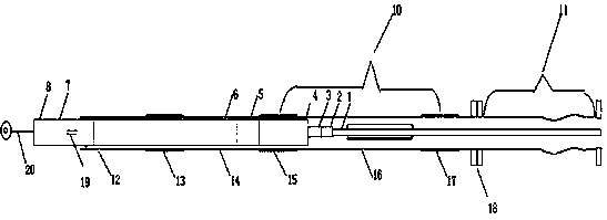
[0038] In order to overcome the lack of an intuitive measurement method for coiled tubing fracturing tool positioning error in the prior art, the existing positioning error measurement method has low accuracy, and the actions of the existing positioning measurement system are all judged by the load signal or electromagnetic signal transmitted to the ground , can not directly observe and measure the problem of the error between the actual spray point and the theoretical spray point, the present invention provides such as Figure 1-4 The described system and method for measuring the positioning error of a coiled tubing fracturing tool for experiments has a reasonable design and high precision, and the experimental data truly reflects the error between the spray point of the spray gun and the design spray point, which is used for later positioning error compensation. It provides a reliable basis and has good reference significance.

[0039] One of the purposes of the present inve...

Embodiment 2

[0050] Based on the above embodiments, in this embodiment, the connector 2 and the fracturing tool 9 are connected through the safety joint 3 .

[0051] The fracturing tool 9 includes a spray gun 4, a packer 6, a positioner 7 and a guide centralizer 8; the spray gun 4, the packer 6, the positioner 7 and the guide centralizer 8 are connected in sequence.

[0052] The positioner 7 is provided with an induction block 19 .

[0053] The guide centralizer 8 at the tail of the fracturing tool 9 is connected with a soft tape 10 .

[0054] The windowing test casing 10 is connected with the short casing two 14 through the casing collar two 15 .

[0055] The second short sleeve 14 is connected to the first short sleeve 12 through the first sleeve collar 13 .

[0056] In this embodiment, the lengths of short casing one 12, short casing two 14, and windowing experimental casing 10 are designed to ensure that after short casing one 12 is connected with short casing two 14 and windowing ex...

Embodiment 3

[0060] Based on the above two embodiments, this embodiment provides image 3 with 4 A method for measuring positioning errors of coiled tubing fracturing tools for experiments, the specific measurement steps are:

[0061] Step 1: Simulate the process of the locator 7 passing through the first casing collar 13 and the second casing collar 15;

[0062] After the coiled tubing 1 is connected with the connector 2, the safety joint 3 and the fracturing tool 9, the coiled tubing 1 and the fracturing tool 9 move back and forth in the short casing 1 12, the short casing 2 14, and the windowing test casing 10, and at the same time , to verify the setting and unsealing performance of the packer 6;

[0063] Lower the fracturing tool 9, expose the sensing block 19 of the positioner 7 to the tail end of the short casing 12, lift the coiled tubing 1 at a speed of 4-5 m / min, and observe that the positioner 7 passes through the casing section collar 1 13 and casing section hoop 2 15 and th...


PUM


Abstract

The invention provides an experimental coiled tubing fracturing tool positioning error measurement system and method. The system comprises a coiled tubing, a connector, a fracturing tool, a first short casing, a second short casing, an open window experiment casing, a third casing coupling, a horizontal shaft and a soft measuring tape. One end of the open window experiment casing is connected withthe horizontal shaft while the other end is connected with the second short casing, and the other end of the second short casing is connected with the first short casing. One end of the fracturing tool is connected with the coiled tubing through the connector, and the other end of the fracturing tool is connected with the soft measuring tape. The coiled tubing is positioned in the open window experiment casing, the fracturing tool is positioned in the second short casing and the first short casing, and the open window experiment casing is provided with an open window portion. Aiming at an opening condition that a sensing block of a positioner is right in a hoop of the second short casing, measured positioning errors are corrected according to an up-flow quantity measuring value in an up-lifting process of the fracturing tool, references are provided, perforation positioning accuracy is improved, and project complexity caused by positioning errors are reduced.

Description

technical field [0001] The invention belongs to the field of positioning error measurement of coiled tubing fracturing perforation, and in particular relates to a positioning error measuring system and method for an experimental coiled tubing fracturing tool. Background technique [0002] At present, in coiled tubing bottom seal dragging staged fracturing operations, vertical wells and directional wells are more and more finely segmented fracturing operations, but the current operating procedures for coiled tubing bottom seal dragging fracturing cannot meet the requirements of vertical wells and directional wells. Due to the demand for positioning error detection in fragmentation fracturing, it is impossible to provide accurate and quantitative error compensation benchmarks for field operations, resulting in downhole complexity caused by positioning errors. [0003] According to research, the existing measurement systems and methods for the positioning error of several coile...

Claims


Application Information

Patent Timeline
IPC IPC(8): E21B47/00E21B43/26E21B43/114E21B43/119E21B29/06E21B17/08
CPCE21B17/08E21B29/06E21B43/114E21B43/119E21B43/26E21B47/00Y02E10/10
Inventor 高森隆世明李星星杨红斌李铭崔向敏陈雄吴简田军
Owner BC P INC CHINA NAT PETROLEUM CORP
Learn More