
Bionic cascade phase change energy storage device

A phase-change energy storage and cascade technology, which is applied in the direction of heat exchange equipment, heat exchanger type, heat storage equipment, etc., can solve the problems of limiting the heat storage capacity of the energy storage plate, slow heat transfer, poor thermal conductivity, etc., and achieve melting Effects of increasing time, increasing movement speed, and improving thermal conductivity

Inactive Publication Date: 2018-11-23
SOUTHEAST UNIV
View PDF6 Cites 12 Cited by
  • Summary
  • Abstract
  • Description
  • Claims
  • Application Information

AI Technical Summary

Problems solved by technology

In addition, because phase change materials generally have the disadvantage of poor thermal conductivity, as the thermal fluid phase change heat process proceeds, the heat transfer is slow, and the phenomenon of incomplete phase change is prone to occur, which limits energy storage to a certain extent. Plate heat storage capacity
Therefore, the phase change material arrangement scheme of the traditional energy storage board is not the best solution for effective heat storage in the actual working environment, and it is urgent to find a new and efficient heat storage scheme and technology

Method used


Image

  • Bionic cascade phase change energy storage device
  • Bionic cascade phase change energy storage device
  • Bionic cascade phase change energy storage device

Examples


Embodiment Construction

[0028] A further detailed description is carried out below in conjunction with the description of the accompanying drawings:

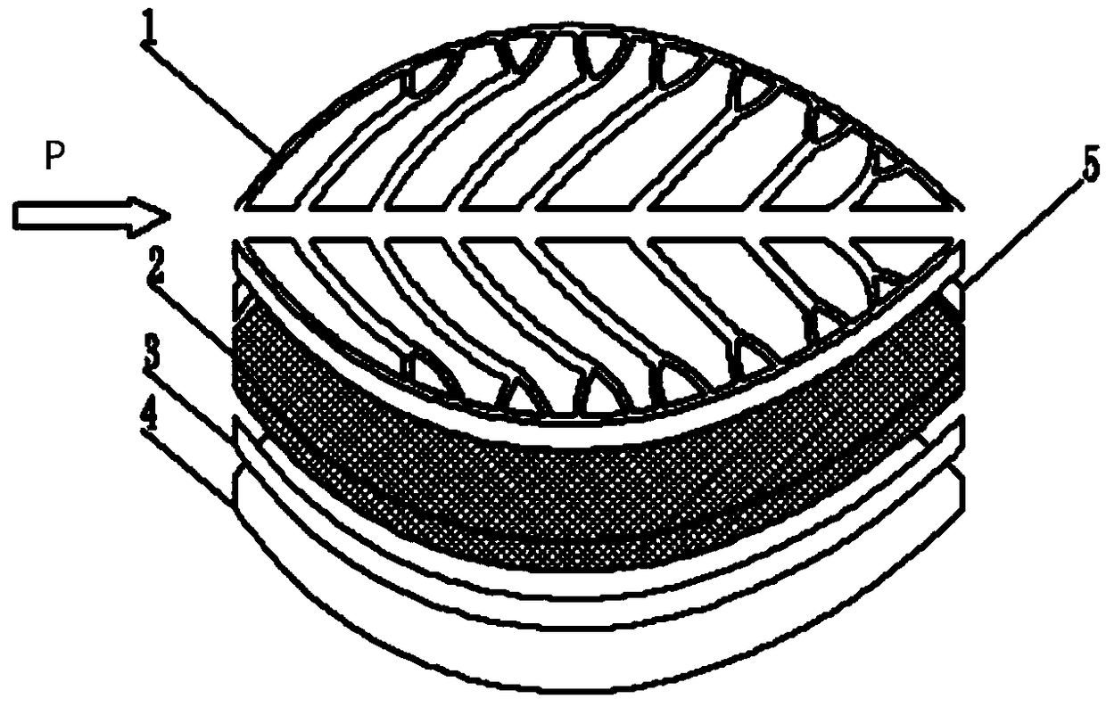
[0029] figure 1 Shown is a three-dimensional structural diagram of a bionic cascade phase change energy storage device with variable porosity optimized perforated frame structure, which is a closed energy storage composed of heat exchange surface 1, lower wall surface 4, rear wall surface 5, front wall surface 3 and perforated frame structure 2 device, the phase change cavity is composed of a metal perforated structure 2 and a phase change material. The heat exchange surface 1 and the lower wall 4 are connected by an annular wall; the pore frame structure in the phase change cavity is composed of sintered foam metal, and the pores filled with phase change materials in the middle are optimized by the porosity algorithm, and the porosity is designed to be high in the middle and low on both sides. Variable porosity structures with intermediate linearly v...


PUM


Abstract

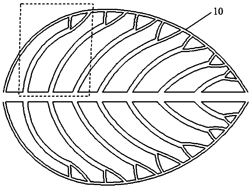
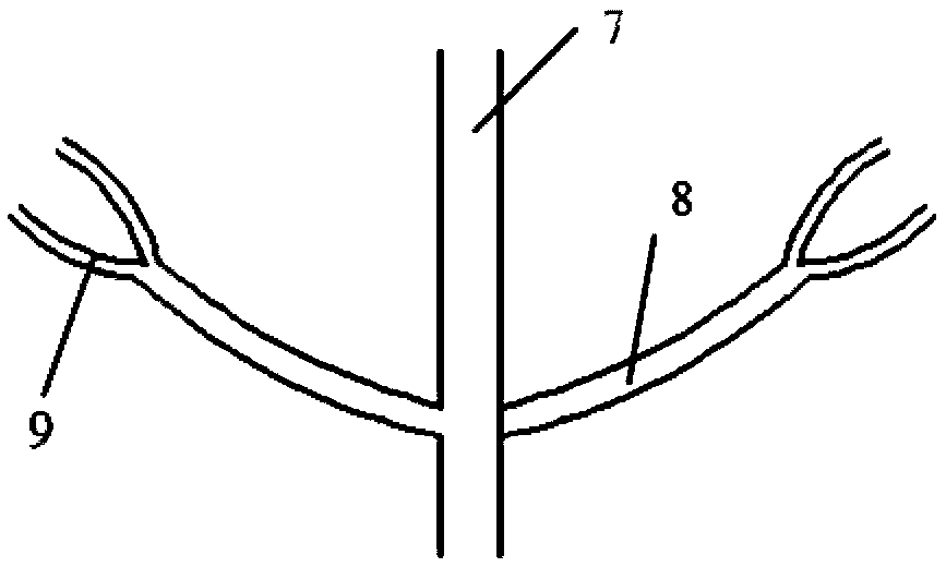
The invention discloses a bionic cascade phase change energy storage device. The bionic cascade phase change energy storage device comprises a heat exchange plate and an energy storage plate in contact with the heat exchange plate for heat exchange. The heat exchange plate is internally provided with bionic cascade flow channels, the bionic cascade flow channels are leaf-shaped bionic cascade bifurcated flow channels, and the bionic cascade flow channels comprise a middle main flow channel body, leaf-shaped bionic cascade bifurcated flow channel bodies and edge flow channel bodies, wherein theleaf-shaped bionic cascade bifurcated flow channel bodies extend along the middle main flow channel body to both sides in a bifurcated mode. The edge flow channel bodies communicate with the tail ends of the leaf-shaped bionic cascade bifurcated flow channel bodies. The energy storage plate is internally provided with a metal hole frame structure and phase change material, wherein the metal holeframe structure is filled with the phase change material, the metal hole frame structure is a foam metal plate with variable porosity, and the porosity of the foam metal plate decreases gradually fromthe middle main flow channel body to both sides. According to the bionic cascade phase change energy storage device, the heat conduction characteristic of the phase change material can be effectivelyimproved, and the heat absorption and release rate and heat storage capacity of the phase change material are enhanced; the heat exchange efficiency with thermal fluid is improved, and energy loss isreduced; and the structure is simple, assembly and disassembly are convenient, and a guarantee for the efficient and reliable operation of an energy system is provided.

Description

technical field [0001] The invention relates to an energy storage device, in particular to a bionic cascade phase change energy storage plate designed for improving phase change energy storage performance and realizing high-efficiency and rapid heat transfer and having algorithm-optimized perforated frame structure features. Background technique [0002] Phase change energy storage technology has excellent energy storage performance due to the phase change heat transfer as the basic heat transfer method, and is widely used in power peak shaving, industrial waste heat recovery, solar thermal utilization and other fields. As a phase change energy storage device, the energy storage board has the advantages of simple structure, good temperature uniformity, good work adaptability, and is conducive to centralized storage of large heat sources. It has broad applications in the fields of thermoelectric energy storage systems and waste heat recovery. Application prospects. [0003] ...

Claims


Application Information

Patent Timeline
IPC IPC(8): F28D20/02F28F21/08
CPCF28D20/025F28F21/081Y02E60/14H01L23/46
Inventor 张程宾陈希
Owner SOUTHEAST UNIV
Learn More