Flaring heat pipe and manufacturing method thereof
A manufacturing method and technology of heat pipes, applied in the field of heat pipes, can solve problems such as complicated procedures and increased production costs, and achieve the effects of obvious reflux cycle, improved heat transfer efficiency, and reduced production costs
- Summary
- Abstract
- Description
- Claims
- Application Information
AI Technical Summary
Problems solved by technology
Method used
Image


Examples
Embodiment 1
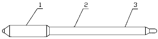
[0037] Such as image 3 Shown, a kind of manufacture method of flared heat pipe, described manufacture method mainly comprises the following steps:
[0038] Step 1: Provide a circular hollow tube body, the length of which is L;
[0039] Step 2: Flare one end of the hollow tube body first, and the length of the flared section is L1; shrink the other end of the hollow tube body to half of the outer diameter of the hollow tube body (the tolerance is plus or minus 0.5mm); The outer diameter of the mouth section is 1.2 times the outer diameter of the hollow tube;
[0040] Step 3: Insert a stainless steel round rod of a certain size into the hollow tube body with a narrow mouth at one end;
[0041] Step 4: Fill metal powder into the hollow tube body inserted into the stainless steel round rod, and sinter at high temperature after the powder filling is completed;
[0042] Step 5: After the sintering is completed, pull out the stainless steel round rod in the hollow tube body; shri...
Embodiment 2
[0046] Such as image 3 Shown, a kind of manufacture method of flared heat pipe, described manufacture method mainly comprises the following steps:
[0047] Step 1: Provide a circular hollow tube body, the length of which is L;
[0048]Step 2: Flare one end of the hollow tube body first, and the length of the flared section is L1; shrink the other end of the hollow tube body to half of the outer diameter of the hollow tube body (the tolerance is plus or minus 0.5mm); The outer diameter of the mouth section is 1.3 times the outer diameter of the hollow tube;
[0049] Step 3: Insert a stainless steel round rod of a certain size into the hollow tube body with a narrow mouth at one end;
[0050] Step 4: Fill metal powder into the hollow tube body inserted into the stainless steel round rod, and sinter at high temperature after the powder filling is completed;
[0051] Step 5: After the sintering is completed, pull out the stainless steel round rod in the hollow tube body; shrin...
Embodiment 3
[0055] Such as image 3 Shown, a kind of manufacture method of flared heat pipe, described manufacture method mainly comprises the following steps:
[0056] Step 1: Provide a circular hollow tube body, the length of which is L;
[0057] Step 2: Flare one end of the hollow tube body first, and the length of the flared section is L1; shrink the other end of the hollow tube body to half of the outer diameter of the hollow tube body (the tolerance is plus or minus 0.5mm); The outer diameter of the mouth section is 1.4 times the outer diameter of the hollow tube;
[0058] Step 3: Insert a stainless steel round rod of a certain size into the hollow tube body with a narrow mouth at one end;
[0059] Step 4: Fill metal powder into the hollow tube body inserted into the stainless steel round rod, and sinter at high temperature after the powder filling is completed;
[0060] Step 5: After the sintering is completed, pull out the stainless steel round rod in the hollow tube body; shri...
PUM
| Property | Measurement | Unit |
|---|---|---|
| Diameter | aaaaa | aaaaa |
Abstract
Description
Claims
Application Information
 - R&D
- Intellectual Property
- Life Sciences
- Materials
- Tech Scout
- Unparalleled Data Quality
- Higher Quality Content
- 60% Fewer Hallucinations
Browse by: Latest US Patents, China's latest patents, Technical Efficacy Thesaurus, Application Domain, Technology Topic, Popular Technical Reports.
© 2025 PatSnap. All rights reserved.Legal|Privacy policy|Modern Slavery Act Transparency Statement|Sitemap|About US| Contact US: help@patsnap.com