
Device for ceramic part casting

A component and ceramic technology, applied in ceramic molding machines, manufacturing tools, auxiliary molding equipment, etc., can solve the problems of broken and cut staff, low production qualification rate, and overall quality reduction, etc., to improve production efficiency and Quality, reduced probability of cracking, improved effect of component force

Inactive Publication Date: 2018-11-23
冯玉凤
View PDF5 Cites 0 Cited by
  • Summary
  • Abstract
  • Description
  • Claims
  • Application Information

AI Technical Summary

Problems solved by technology

[0003] Aiming at the deficiencies in the prior art, the object of the present invention is to provide a device for casting ceramic parts to solve the problem that the injection molding of the device for casting ceramic parts requires internal space pressure, and the action force and reaction force of space mechanics are relatively Yes, so in the process of pressure casting, ceramics are fragile products, and its parts are easily cracked by the reaction of pressure, resulting in cumbersome operations to repair cracks in later processing, and also reduce the overall quality, the production pass rate is not high, and the tortoise The cracked lines are easy to break and cut the staff when they are collided, which poses a safety hazard

Method used


Image

  • Device for ceramic part casting
  • Device for ceramic part casting
  • Device for ceramic part casting

Examples


Embodiment Construction

[0024] In order to make the technical means, creative features, goals and effects achieved by the present invention easy to understand, the present invention will be further described below in conjunction with specific embodiments.

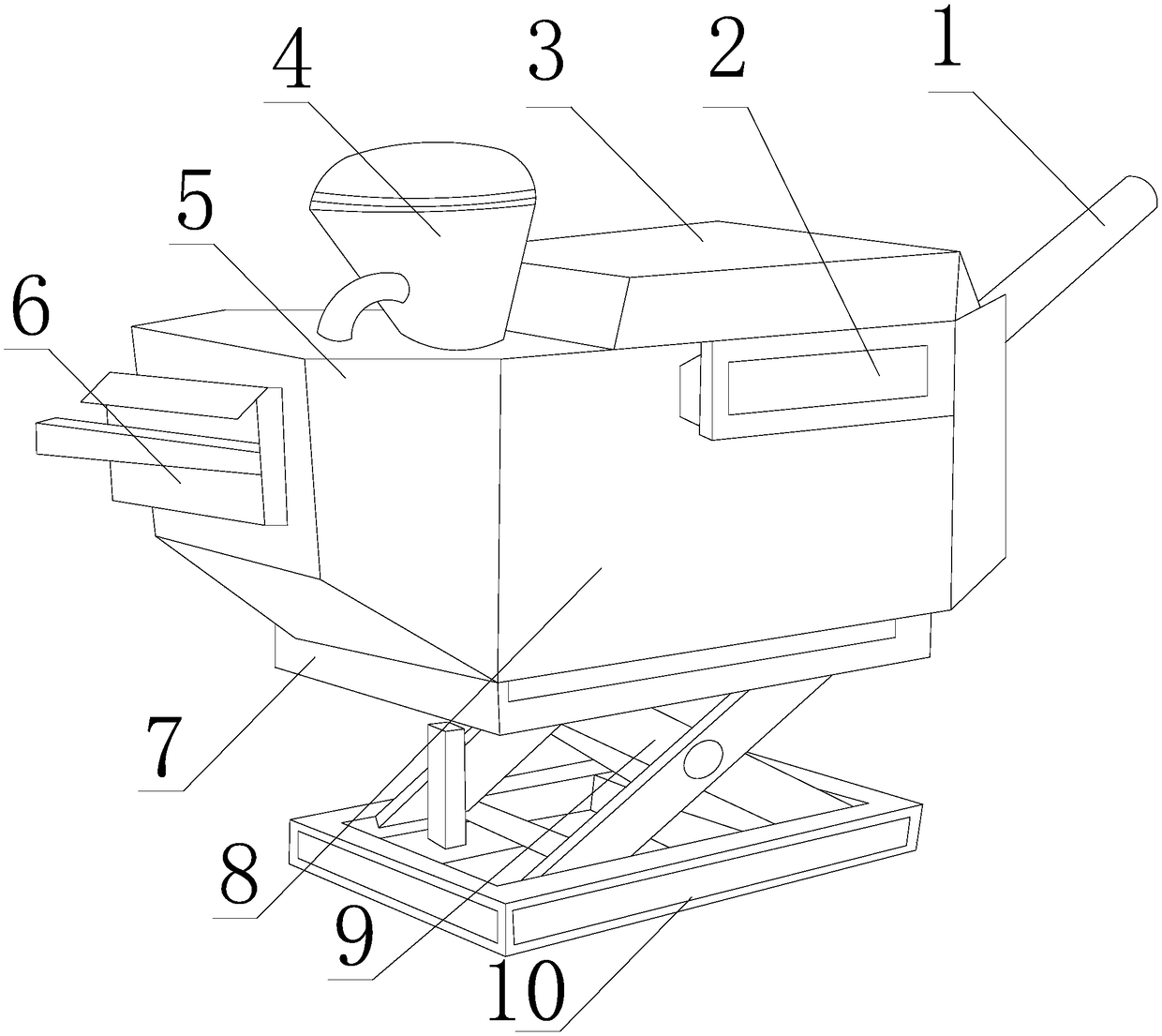
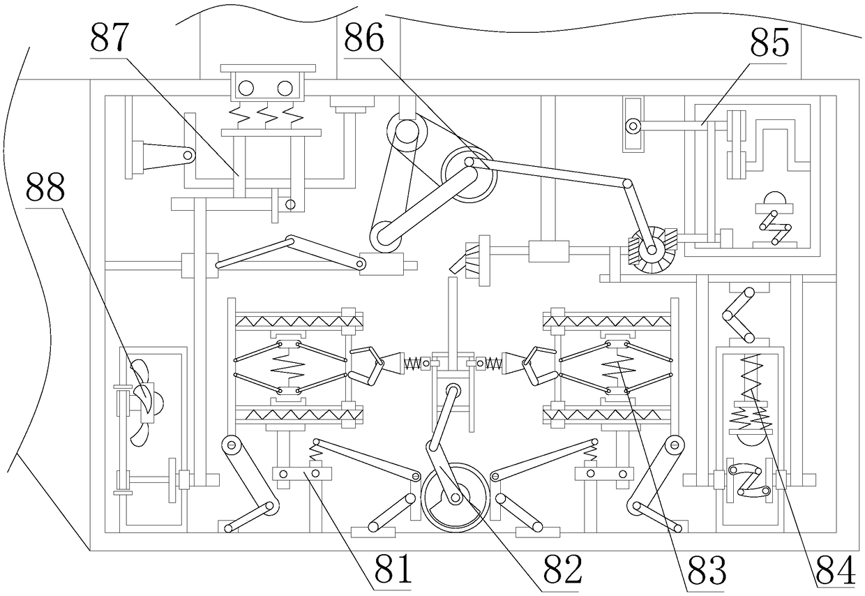
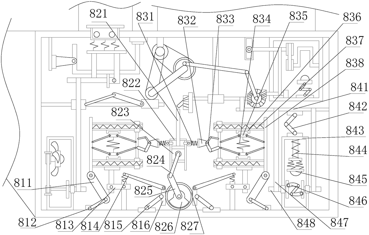
[0025] see Figure 1-Figure 5 , the present invention provides a device for casting ceramic parts, the structure of which includes: an exhaust pipe 1, a buckle splint 2, a material spreading block 3, a water injection tank 4, a discharge chute 5, a tie rod square groove 6, a bracket Platform base 7, anti-pressurization casting box 8, folding bracket 9, base block 10, the water injection tank 4 is inserted in the upper left corner of the anti-pressurization casting box 8 and communicates with each other, the bottom surface of the spreading press block 3 Closely attached to the top surface of the anti-pressurization casting box 8, the exhaust pipe 1 is inserted on the right side of the anti-pressurization casting box 8 at an angle of 45 degrees, and...


PUM


Abstract

The invention discloses a device for ceramic part casting. The device for ceramic part casting structurally comprises an exhaust pipeline, a buckle clamping plate, a material paving pressing block, awater injecting tank, a discharging inclined groove, a pulling rod square groove, a supporting table base, a reverse supercharging casting box, a foldable support and a base block; the water injectiontank is inserted and embedded in the upper left corner of the reverse supercharging casting box and communicates with the upper left corner of the reverse supercharging casting box; and the bottom face of the material paving pressing block is closely attached to the top face of the reverse supercharging casting box. According to the device, the reverse supercharging casting box is provided with arod piece support, an internal combustion cylinder device, a spring push frame, a reverse supercharging mechanism, a rotating device, a traction mechanism, a pressure drop groove base and a fan device, the force unloading reverse supercharging effect of the device for ceramic part casting is achieved, the space position of ceramic parts is improved, buffered force unloading is achieved due to left-right clamping, upward reverse supercharging casting molding is achieved, the probability of cracking is lowered, and therefore the labor consumed during later period repairing of cracks is lowered,the production efficiency and quality are improved, pressure is pushed into ceramic better to make the ceramic solidify, and the force dispersing effect on the counter-acting force is improved.

Description

technical field [0001] The invention relates to a device for casting ceramic parts, which belongs to the field of ceramic casting devices. Background technique [0002] Sand casting is a casting method for producing castings in sand molds. Steel, iron and most non-ferrous alloy castings can be obtained by sand casting methods. Because the molding materials used in sand casting are cheap and easy to obtain, the casting molds are easy to manufacture. Production, batch production and mass production can be adapted. For a long time, it has been the basic process in foundry production. The outer sand mold used in sand casting is divided into clay green sand mold according to the binder used in the sand and the way to build its strength. , clay dry sand mold and chemically hardened sand mold. The principles and methods of ceramic casting molds and plaster casting molds are very similar, but the materials are different. When using ceramic molds, inject ceramic base mud into the mol...

Claims


Application Information

Patent Timeline
Patent Type & Authority Applications(China)
IPC IPC(8): B28B1/54B28B17/00
Inventor 冯玉凤
Owner 冯玉凤
Learn More