Rock deforming and cracking three-dimensional dynamic testing system based on fiber strain sensing

A fiber optic strain and three-dimensional dynamic technology, applied in the direction of applying stable tension/pressure to test the strength of materials, measuring devices, using optical devices, etc., can solve the problem of poor anti-interference effect, can only be pasted on the rock surface, cannot be completed, etc. question

Inactive Publication Date: 2011-10-26
SHANDONG UNIV
View PDF3 Cites 0 Cited by
  • Summary
  • Abstract
  • Description
  • Claims
  • Application Information

AI Technical Summary

Problems solved by technology

How to carry out the rock compression-shear composite fracture problem under the simultaneous action of rock compressive stress and shear stress, at present, mathematical mechanics theory analysis and numerical simulation methods are widely used, and some experimental methods are mostly made of similar materials. Approximation and simplification are difficult to achieve the effect of obtaining the deformation and fracture process of real rocks and the evolution law of rock defects, and traditional experiments use strain gauges pasted on real rock specimens for testing, while strain gauges can only be pasted on the rock surface. It is difficult to measure if it goes deep into the rock, and at the same time, the laying effect of the strain gauge on the rock and the anti-interference effect are worse than that of the optical fiber strain sensor. The optical fiber strain sensor mainly refers to the fiber grating sensor and the long period grating sensor in this design. Literature (Underground Space and Engineering Journal, Volume III, No. 6, December 2007) used optical fiber sensing to measure the surface strain of rock specimens of similar materials, but they used bare fiber gratings embedded in the plane model of similar simulation materials, There are also some materials that embed fiber grating sensors in reinforced concrete specimens, or paste them on the surface of rock specimens of different shapes to test unidirectional strain.
Due to the large difference between the rock test piece and the real rock test, they can only obtain approximate data of the rock. If they want to obtain the three-dimensional fracture dynamic process of the rock, they can obtain the real experimental data of the rock under triaxial pressure, and construct the rock visually. image of the rupture process, it is not possible to complete

Method used


Image

  • Rock deforming and cracking three-dimensional dynamic testing system based on fiber strain sensing
  • Rock deforming and cracking three-dimensional dynamic testing system based on fiber strain sensing
  • Rock deforming and cracking three-dimensional dynamic testing system based on fiber strain sensing

Examples


Embodiment 1

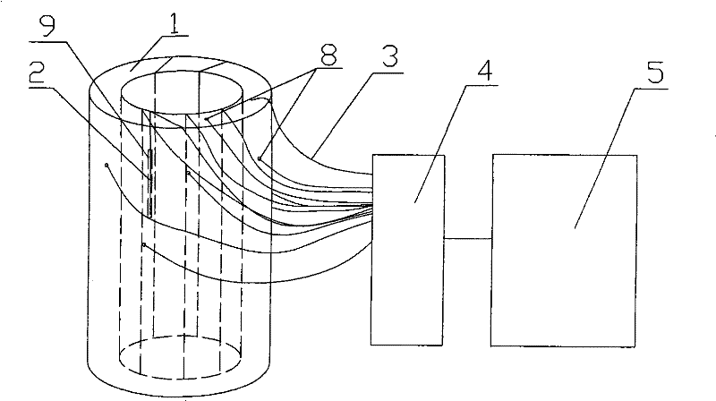
[0020] Example 1: figure 1 Among them, the test piece 1 is cylindrical, and its outer side and end surface are respectively provided with a number of micro-holes 8, and the cylinder inner wall, outer side and end surface of the test piece 1 are also provided with a number of long micro-grooves 9, fiber grating sensor 2 are respectively laid in the micro-hole 8 and the long micro-groove 9, and evenly arranged on the inner surface of the cylinder of the test piece 1; the fiber grating sensor 2 arranged on the outer side and end surface of the test piece 1 is sealed and sealed with high-strength glue Fixed to ensure effective coupling between the fiber grating sensor 2 and the surface of the rock specimen 1. The fiber grating sensor 2 is connected to the optical switch 4 through the optical fiber 3, and the optical switch 4 is connected to the fiber demodulation instrument 5. The fiber grating sensor 2 in the microhole 8 is mainly used to test the strain changes in the internal hor...

Embodiment 2

[0021] Example 2: Such as figure 2 As shown, the test piece 1 is cylindrical, the outer side and end surface of the test piece 1 are provided with a number of micro-holes 8, and the inner wall, the outer side and the end surface of the test piece 1 are provided with a number of long micro-grooves 9, long period The grating 6 is laid on the inner surface of the cylinder and in the micro-holes 8 and long micro-grooves 9 on the inner wall, outer side and end surface of the cylinder. One end of the long-period grating 6 is a broadband light source, and the other end is connected to a spectrum analyzer 7 for Analyze the transmission spectrum of the long period grating. The long-period grating 6 in the microhole 8 is mainly used to test the strain changes in the internal horizontal (ie X and Y directions) direction; the long-period grating 6 in the long microgrooves 9 on the inner and outer surfaces of the specimen 1 is mainly used To test the strain change in the vertical (Z direct...

Embodiment 3

[0022] Example 3: Specimen 1 is square, and the outer surface of specimen 1 is provided with a number of micro-holes 8 and a number of long micro-grooves 9, long-period grating 6 is laid in the micro-holes 8 and the long micro-grooves 9, long-period grating One end of 6 is a broadband light source, and the other end is connected to a spectrum analyzer 7 for analyzing the transmission spectrum of the long period grating.

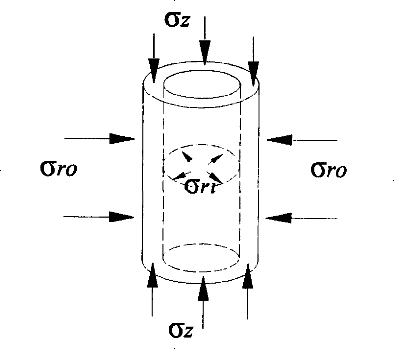
[0023] In the present invention image 3 Indicates the direction of the pressure exerted by the three-axis press on the specimen. The specimen is placed in a sealed pressure chamber, and the upper and lower ends of the specimen are compressed by σ z , The inside of the test piece is filled with high-pressure oil and sealed, causing outward pressure σ rl , After the outer surface of the test piece is sealed by external high-pressure oil, an inward pressure σ is generated ro .

[0024] Figure 4 It is a process of applying a fiber grating sensor in a long micro-groov...


PUM


Abstract

The invention relates to a rock deforming and cracking three-dimensional dynamic testing system based on fiber strain sensing, which comprises a testing piece, wherein the testing piece is laid with aThe invention relates to a rock deforming and cracking three-dimensional dynamic testing system based on fiber strain sensing, which comprises a testing piece, wherein the testing piece is laid with afiber sensor encapsulated with a plurality of testing strains; the fiber sensor is connected with a signal demodulation processing device through a connecting fiber; and demodulated data signals can fiber sensor encapsulated with a plurality of testing strains; the fiber sensor is connected with a signal demodulation processing device through a connecting fiber; and demodulated data signals canbuild three-dimensional testing data of the testing piece and can form a three-dimensional dynamic strain field of the testing piece after interpolation. The system can effectively lay out the fiber sbuild three-dimensional testing data of the testing piece and can form a three-dimensional dynamic strain field of the testing piece after interpolation. The system can effectively lay out the fiber sensor inside and on the surface of the real rock testing piece under the pressure of a three-axis presser, enters the rock inside to detect the rock dynamic strain under the premise of not influencingensor inside and on the surface of the real rock testing piece under the pressure of a three-axis presser, enters the rock inside to detect the rock dynamic strain under the premise of not influencing the rock structure and the stress, and can really test the rock dynamic cracking process to obtain the crack initial and expended spatial positions inside the testing piece. The system continuously mthe rock structure and the stress, and can really test the rock dynamic cracking process to obtain the crack initial and expended spatial positions inside the testing piece. The system continuously monitors the generation and expansion of tiny cracks inside brittle materials under the loading action in real time at the same time, and can be widely applied to researching cracking instability mechaonitors the generation and expansion of tiny cracks inside brittle materials under the loading action in real time at the same time, and can be widely applied to researching cracking instability mechanisms of materials, such as rocks, concrete and the like.nisms of materials, such as rocks, concrete and the like.

Description

Technical field [0001] The invention relates to a rock deformation and fracture dynamic testing device, in particular to a rock deformation and fracture three-dimensional dynamic testing system based on optical fiber strain sensing. Background technique [0002] Deformation and fracture of rock is an important mechanical characteristic of rock. Rock is an anisotropic medium containing initial defects such as pores, cracks and microstructure planes. Under external load, the initial defect closure of the rock and the initiation and propagation of microcracks determine the deformation of the rock. Feature. In the study of rock engineering mechanics, except for a few deformations and forces that can be simplified into two-dimensional models of plane problems or axisymmetric problems for processing, due to the existence of inhomogeneities in rocks and rock masses, asymmetric failure is easy to occur . When it comes to asymmetry damage, almost all two-dimensional damage problems becom...

Claims


Application Information

Patent Timeline
Patent Type & Authority Patents(China)
IPC IPC(8): G01B11/16G01N3/08
Inventor 蒋奇李术才李树忱
Owner SHANDONG UNIV
Why Eureka
Try Eureka