
Machining chip removing method

A technology for mechanical processing and workpieces, which is applied in the field of mechanical processing and chip removal, which can solve the problems of troublesome cleaning by staff, inability of staff to observe closely, and metal debris splashing everywhere, so as to prevent splashing everywhere, facilitate cleaning and low production cost Effect

Active Publication Date: 2018-11-23
CHUZHOU KEXIN MECHANICAL TECH
View PDF8 Cites 5 Cited by
  • Summary
  • Abstract
  • Description
  • Claims
  • Application Information

AI Technical Summary

Problems solved by technology

[0003] In the process of metal cutting, drilling and other mechanical processing, a large amount of metal debris will be generated, and these metal debris will splash around, making it impossible for the staff to observe closely, and the splashed metal debris will fall on each part of the machine. It is very troublesome for the staff to clean the corners. Therefore, we propose a method of mechanical processing to remove dandruff

Method used


Image

  • Machining chip removing method
  • Machining chip removing method
  • Machining chip removing method

Examples


Embodiment

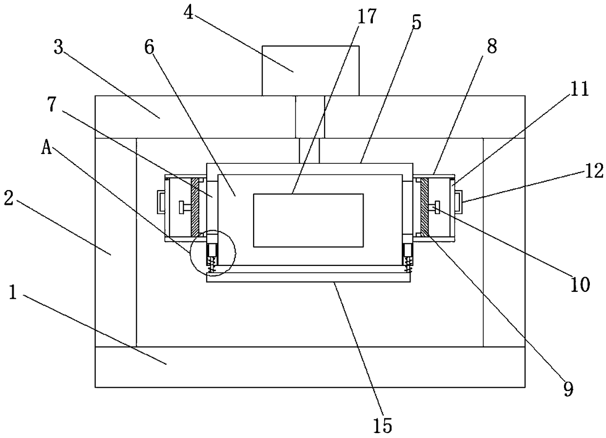
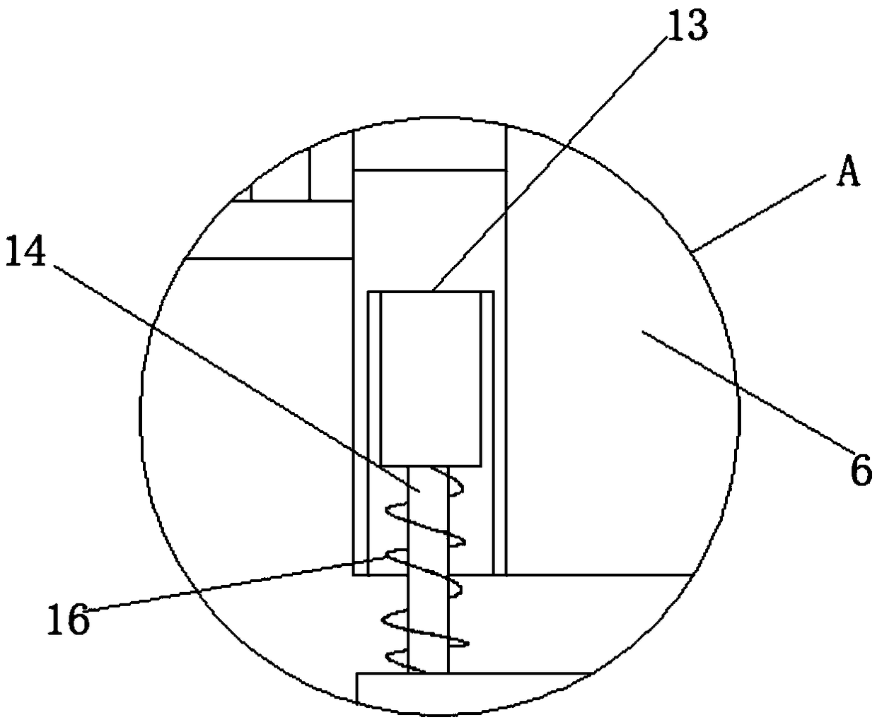
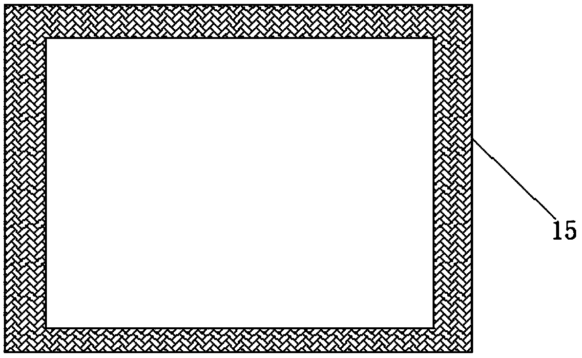
[0020] Embodiment: the processing tool is installed inside the first groove 6, the workpiece is placed on the surface of the first support plate 1, the cylinder 4 is started, the cylinder 4 pushes the fixed plate 5, the fixed plate 5 drives the pressure plate 15 to squeeze the workpiece, and as the fixed As the plate 5 moves downward, the tool will process the workpiece, and the metal chips generated during the processing will enter the collection box 8 through the first through hole 7 and be adsorbed on the surface of the magnet 9, and the remaining metal chips will remain in the first through hole 7 The inside of a groove 6 prevents splashing everywhere and is convenient for people to clean up. The transparent observation window 17 provided is convenient for people to observe at a close distance. The position is offset, which improves the machining accuracy. Finally, the baffle 11 is opened, and the push plate 10 is pulled. The push plate 10 drives the magnet 9 to move out of...


PUM


Abstract

The invention discloses a machining chip removing method. According to the machining chip removing method, a machining cutter is installed inside a first groove (6), a workpiece is placed on the surface of a first supporting plate (1), an air cylinder (4) is started and pushes a fixing plate (5), the fixing plate (5) drives a pressing plate 15 to squeeze the workpiece, along with downward movementof the fixing plate (5), the cutter machines the workpiece, a part of metal chips generated in the machining process enters collection boxes (8) via first through holes (7) and are attracted on the surfaces of magnets (9), the remaining metal chips remain inside the first groove (6), baffles (11) are opened finally, push plates (10) are pulled, the push plates (10) drive the magnets (9) to move out of the collection boxes (8), and the metal chips on the surfaces of the magnets (9) are collected. By the adoption of the machining chip removing method, the metal chips generated in the machiningprocess can be rapidly collected, the metal chips can be prevented from splashing all around, and people can conveniently clean the metal chips.

Description

technical field [0001] The invention relates to the technical field of mechanical processing, in particular to a method for removing chips in mechanical processing. Background technique [0002] The production process of a machine refers to the entire process of making a product from raw materials (or semi-finished products). For machine production, it includes transportation and storage of raw materials, production preparation, blank manufacturing, processing and heat treatment of parts, product assembly, debugging, painting and packaging, etc. The content of the production process is very extensive. Modern enterprises use the principles and methods of systems engineering to organize and guide production, and regard the production process as a production system with input and output. [0003] In the process of metal cutting, drilling and other mechanical processing, a large amount of metal debris will be generated, and these metal debris will splash around, making it impos...

Claims


Application Information

Patent Timeline
IPC IPC(8): B23Q3/08B23Q11/00
CPCB23Q3/08B23Q11/0064B23Q2703/04
Inventor 吴孝奎李明防李宣春
Owner CHUZHOU KEXIN MECHANICAL TECH
Learn More