
Laser cutting machine used for machining LED light guide board and convenient to adjust

A technology of laser cutting machine and laser cutting head, which is applied in the direction of laser welding equipment, metal processing equipment, manufacturing tools, etc. It can solve the problems of not being able to cut plates quickly and smoothly, the workbench is not flexible enough, and the structure is not simple enough to meet the requirements of precision. Degree requirements, improved flexibility, and the effect of safe work

Inactive Publication Date: 2018-11-20
巩同庆
View PDF9 Cites 3 Cited by
  • Summary
  • Abstract
  • Description
  • Claims
  • Application Information

AI Technical Summary

Problems solved by technology

[0003] With the widespread use of LED, better technology is still needed to support the processing. As far as the current laser cutting machine is concerned, the workbench is not flexible enough to cut the plate quickly and smoothly. At the same time, the cutting direction is relatively fixed and the work efficiency is low. , the structure is not simple enough, and the operation is also very complicated

Method used


Image

  • Laser cutting machine used for machining LED light guide board and convenient to adjust
  • Laser cutting machine used for machining LED light guide board and convenient to adjust
  • Laser cutting machine used for machining LED light guide board and convenient to adjust

Examples


Embodiment Construction

[0021] The following will clearly and completely describe the technical solutions in the embodiments of the present invention with reference to the accompanying drawings in the embodiments of the present invention. Obviously, the described embodiments are only some, not all, embodiments of the present invention.

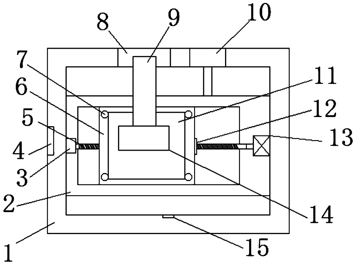
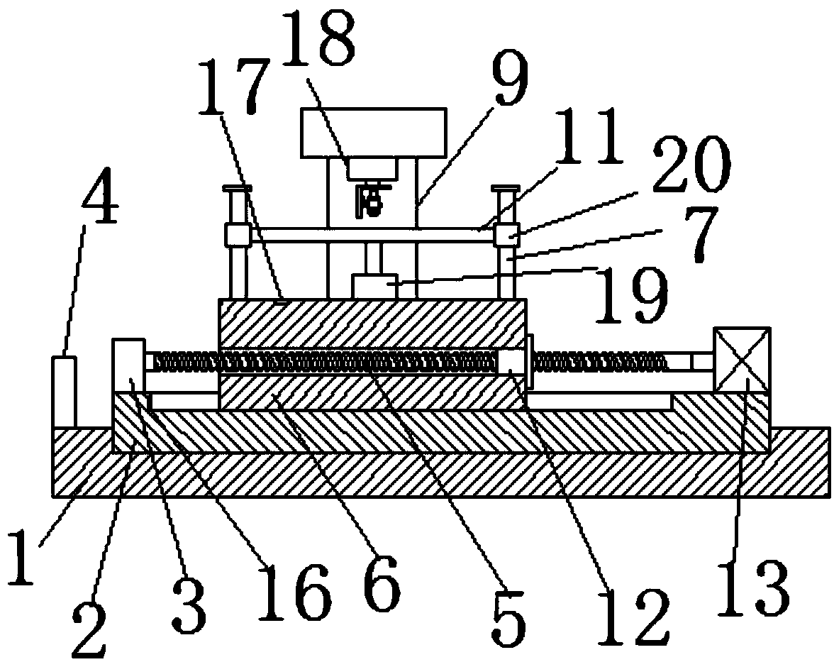
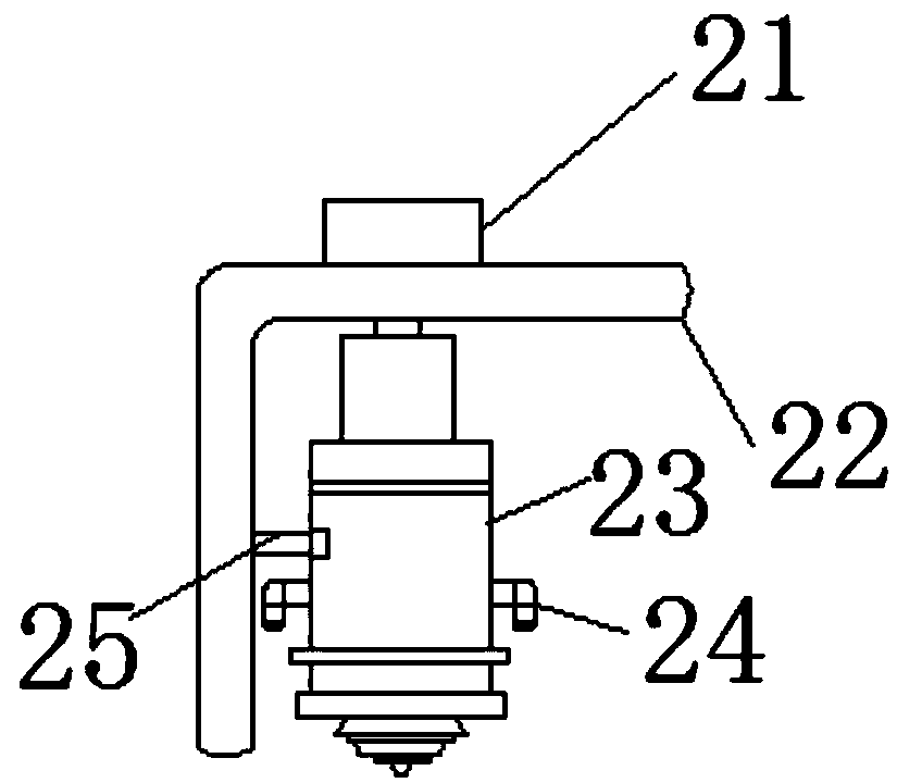
[0022] refer to Figure 1-3 , a laser cutting machine for easy adjustment of LED light guide plate processing, including a base 1, a first sliding groove is opened on the top outer wall of the base 1, and a first mobile platform 2 is slidably connected to the inner wall of the first sliding groove, and the top outer wall of the base 1 The display 4 is fixed by screws, the top outer wall of the base 1 is fixed with the first hydraulic cylinder 10 by screws, and one end of the extension rod of the first hydraulic cylinder 10 is fixed with the first mobile platform 2 by screws, which greatly improves the flexibility of the device The inner wall of the first sliding groo...


PUM


Abstract

The invention discloses a laser cutting machine used for machining an LED light guide board and convenient to adjust. The laser cutting machine comprises a base. A first sliding groove is formed in the outer wall of the top of the base. A first moving platform is connected to the inner wall of the first sliding groove in a sliding manner. A displayer is fixed to the outer wall of the top of the base through screws. A first hydraulic cylinder is fixed to the outer wall of the top of the base through screws. A first moving platform is fixed to one end of an extending rod of the first hydraulic cylinder through screws. A first installing groove is formed in the inner wall of one side, away from the first hydraulic cylinder, of the first sliding groove. A first distance inductor is fixed to the inner wall of the first installing groove through screws. A second sliding groove is formed in the outer wall of the top of the first moving platform. A second moving platform is connected to the inner wall of the second sliding groove in a sliding manner. According to the laser cutting machine, a working table can move freely in the X direction, the Y direction and the Z direction, the flexibility of the device is improved greatly, and the cutting error and the cutting fault are reduced.

Description

technical field [0001] The invention relates to the technical field of laser cutting machines, in particular to a laser cutting machine which is used for processing LED light guide plates and is easy to adjust. Background technique [0002] The LED light guide plate is based on optical grade acrylic, using LCD display and backlight module technology, through the high light transmittance of the light guide point, the light guide point is designed by the computer so that the light of the light guide plate is converted into a surface light source uniform light State Manufacturing Molding. Laser cutting process replaces the traditional mechanical knife with an invisible beam. It has the characteristics of high precision, fast cutting, not limited to cutting patterns, automatic typesetting saves materials, smooth incision, and low processing cost. It will gradually improve or replace it. Traditional metal cutting process equipment. [0003] With the widespread use of LED, bette...

Claims


Application Information

Patent Timeline
Patent Type & Authority Applications(China)
IPC IPC(8): B23K26/08B23K26/38B23K26/70
CPCB23K26/0853B23K26/38B23K26/702
Inventor 巩同庆
Owner 巩同庆
Learn More