
Electric furnace transformer body structure for preventing transformer windings from being overheated locally

An electric furnace transformer and transformer winding technology, applied in the field of transformers, can solve the problems of less turns, affect the characteristics of the transformer, damage the transformer, etc., and achieve the effects of being beneficial to heat exchange and dissipation, preventing uneven current distribution, and eliminating local overheating.

Inactive Publication Date: 2018-11-16
江苏鑫航电力设备工程有限公司
View PDF0 Cites 1 Cited by
  • Summary
  • Abstract
  • Description
  • Claims
  • Application Information

AI Technical Summary

Problems solved by technology

[0002] Electric furnace transformer is a transformer designed to provide power for various electric furnaces. For large-capacity electric furnace transformers, the low-voltage windings in the transformer have the characteristics of low voltage, large current, and few turns. During the working process, the low-voltage windings in the transformer are easy to Partial overheating occurs at the end of the winding. Long-term overheating of the winding will not only affect the characteristics of the transformer itself, but also damage the transformer, and even cause danger of explosion.

Method used


Image

  • Electric furnace transformer body structure for preventing transformer windings from being overheated locally
  • Electric furnace transformer body structure for preventing transformer windings from being overheated locally

Examples


Embodiment Construction

[0014] The present invention will be further described in detail below in conjunction with the accompanying drawings and specific embodiments.

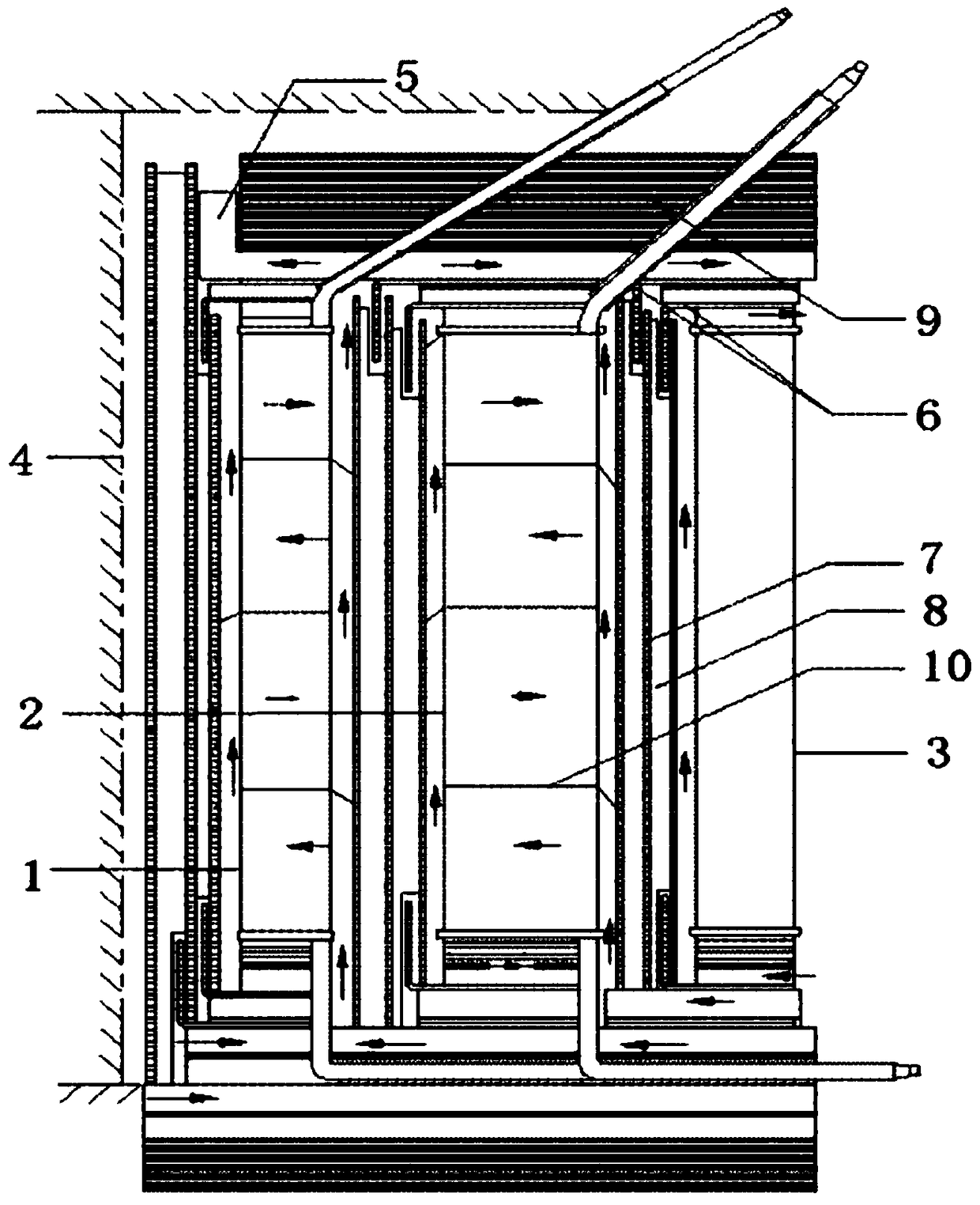
[0015] Such as figure 1 As shown, it is a structural schematic diagram of an electric furnace transformer body structure for preventing partial overheating of transformer windings in the present invention, including a high-voltage phase-shifting winding 1, a high-voltage basic winding 2, a low-voltage winding 3, an iron core 4 and an insulation and heat dissipation system; the iron core 4 The outward installation sequence is high-voltage phase-shifting winding 1, high-voltage basic winding 2 and low-voltage winding 3; the insulation and heat dissipation system is distributed and installed around high-voltage phase-shifting winding 1, high-voltage basic Road parallel double pie structure.

[0016] This design places the low-voltage winding 3 on the outermost side of the transformer body, so that the low-voltage winding 3 is in contact...


PUM


Abstract

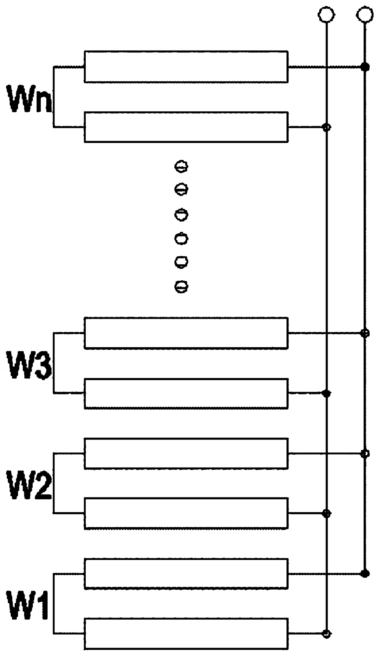
The invention discloses an electric furnace transformer body structure for preventing transformer windings from being overheated locally, and relates to the technical field of structural design of transformer structures. The electric furnace transformer body structure comprises the high-voltage phase-shifting windings, the high-voltage basic windings, the low-voltage windings, an iron core and insulated heat dissipating systems; the high-voltage phase-shifting windings, the high-voltage basic windings and the low-voltage windings are sequentially installed from the iron core to the outside; the insulated heat dissipating systems are distributed at the peripheries of the high-voltage phase-shifting windings, the high-voltage basic windings and the low-voltage windings; the low-voltage windings are located at the outermost side of a transformer body, and the low-voltage windings are in contact with insulated oil close to the outer side of the transformer body. Since the temperature of the insulated oil at the outer side of the transformer body is low, heat exchange and dissipation are better facilitated, heat generated by the low-voltage windings is timely dissipated, and the phenomenon that the low-voltage windings are overheated is avoided; a multipath parallel dual-cake-type structure is adopted for the low-voltage windings, the density of current generated by the low-voltagewindings is uniform, and the phenomenon that the low-voltage windings are locally overheated when the current is not uniformly distributed is avoided.

Description

technical field [0001] The invention relates to the technical field of transformers, in particular to an electric furnace transformer body structure for preventing partial overheating of transformer windings. Background technique [0002] Electric furnace transformer is a transformer designed to provide power for various electric furnaces. For large-capacity electric furnace transformers, the low-voltage windings in the transformer have the characteristics of low voltage, large current, and few turns. During the working process, the low-voltage windings in the transformer are easy to Partial overheating occurs at the end of the winding. Long-term overheating of the winding will not only affect the characteristics of the transformer itself, but also damage the transformer, and even cause an explosion. Contents of the invention [0003] The technical problem to be solved by the present invention is to provide an electric furnace transformer body structure that prevents local...

Claims


Application Information

Patent Timeline
Patent Type & Authority Applications(China)
IPC IPC(8): H01F27/12H01F27/28H01F27/32
CPCH01F27/12H01F27/2823H01F27/321H01F27/322H01F27/324
Inventor 刘英
Owner 江苏鑫航电力设备工程有限公司
Learn More