
Power generation device of new-energy vehicle and method thereof

A new energy vehicle and power generation device technology, applied in the direction of noise reduction devices, exhaust devices, engine components, etc., can solve the problems of power battery limited power, energy loss, poor battery life, etc., to improve service life, improve efficiency, isolate The effect of partial vibration

Active Publication Date: 2018-11-16
蒋祥初
View PDF7 Cites 3 Cited by
  • Summary
  • Abstract
  • Description
  • Claims
  • Application Information

AI Technical Summary

Problems solved by technology

[0002] Compared with traditional internal combustion locomotives, electric new energy vehicles have the advantages of good acceleration performance, quietness and smoothness, and no pollution emissions; however, the power battery on new energy vehicles is limited, so electric new energy vehicles have poor endurance compared with traditional internal combustion locomotives; and A portable internal combustion engine generator can be used as a backup power source for electric new energy vehicles when the battery is exhausted; the exhaust gas of the existing internal combustion engine generator actually contains a large amount of impact kinetic energy and heat energy, and if it is discharged directly, it will cause energy loss

Method used


Image

  • Power generation device of new-energy vehicle and method thereof
  • Power generation device of new-energy vehicle and method thereof
  • Power generation device of new-energy vehicle and method thereof

Examples


Embodiment Construction

[0025] The present invention will be further described below in conjunction with the accompanying drawings.

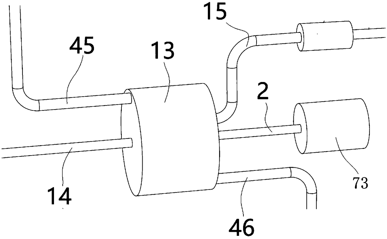
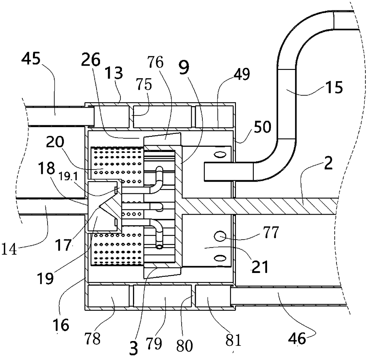
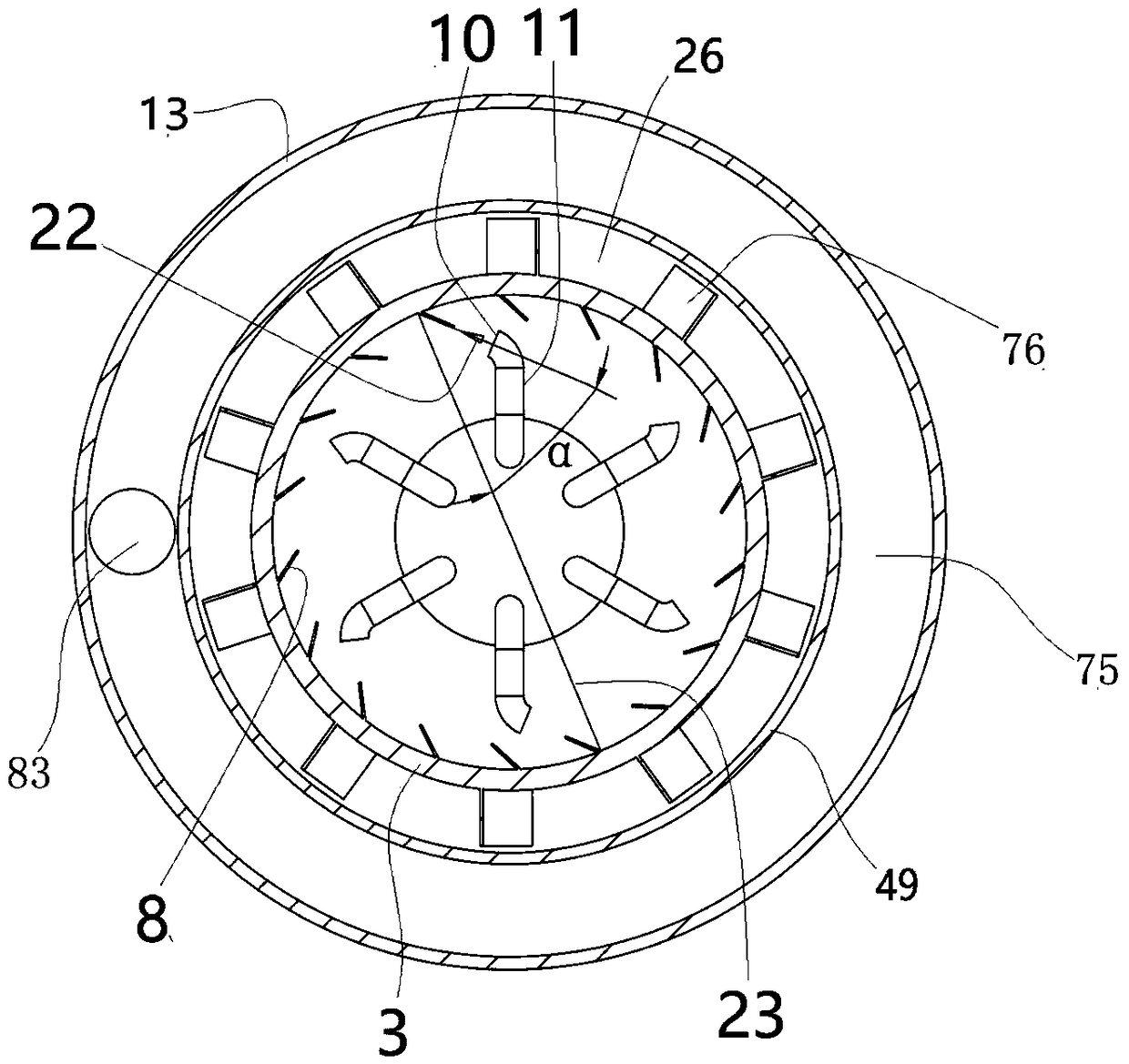
[0026] (1) Introduction to the structure of this plan: as attached Figures 1 to 7 The power generation device of the new energy vehicle shown includes a cylindrical inner casing 49, and the inner cavity of the inner casing 49 is the exhaust gas transducing cavity 6;

[0027] A rotating impeller 3 is arranged coaxially inside the exhaust gas transducing chamber 6, and the rotating impeller 3 is a ring cylindrical structure coaxial with the exhaust gas transducing chamber 6, and the rotating impeller 3 and the inner A flue gas heat exchange channel 26 is formed between the inner walls of the housing 49; the conversion impeller 3 sequentially includes a left ring body 41, a middle ring body 42 and a right ring body 43 which are integrally connected along the axial direction;

[0028] The coaxial center between the middle ring body 42 and the right ring body 43 is integr...


PUM


Abstract

The invention discloses a power generation device of a new-energy vehicle. The power generation device of the new-energy vehicle comprises a cylindrical inner shell. An inner cavity of the inner shellis a tail gas energy-converting cavity. A rotating impeller is coaxially arranged in the tail gas energy-converting cavity. The rotating impeller is of a ring body cylindrical structure coaxial withthe tail gas energy-converting cavity. A smoke heat exchange channel is formed between the rotating impeller and the inner wall of the inner shell. The rotating impeller sequentially comprises a leftring body, a middle ring body and a right ring body in the axial direction, wherein the left ring body, the middle ring body and the right ring body are connected in an integrated manner. The power generation device of the new-energy vehicle is simple in structure, in the process that air sequentially passes through a left ring cavity, a middle ring cavity and a right ring cavity, a large amount of heat released by high-temperature tail gas in the inner shell is absorbed by the air flowing in the left ring cavity, the middle ring cavity and the right ring cavity, and then the effect of preheating the air which is about to enter an intake valve of an engine is achieved.

Description

technical field [0001] The invention belongs to the field of new energy vehicles, in particular to a power generation device and a method for the new energy vehicles. Background technique [0002] Compared with traditional internal combustion locomotives, electric new energy vehicles have the advantages of good acceleration performance, quietness and smoothness, and no pollution emissions; however, the power battery on new energy vehicles is limited, so electric new energy vehicles have poor endurance compared with traditional internal combustion locomotives; and Portable internal combustion engine generators can be used as a backup power source for electric new energy vehicles when the battery is exhausted; the exhaust of existing internal combustion engine generators actually contains a large amount of impact kinetic energy and heat energy, and if it is discharged directly, it will cause energy loss. Contents of the invention [0003] Purpose of the invention: In order t...

Claims


Application Information

Patent Timeline
Patent Type & Authority Applications(China)
IPC IPC(8): F01N5/02F01N5/04F01D15/10
CPCF01D15/10F01N5/02F01N5/04Y02T10/12
Inventor 崔秀萍
Owner 蒋祥初
Learn More