
Robot 3D vision hand-eye calibration method

A hand-eye calibration and robot technology, which is applied in the field of robot 3D vision hand-eye calibration, can solve the problems that the accuracy is difficult to meet the requirements, the accuracy is not enough, and the physical accuracy requirements are very high, and the effect of meeting the accuracy requirements and improving the accuracy is achieved.

Active Publication Date: 2018-11-16
苏州汉振深目智能科技有限公司
View PDF6 Cites 19 Cited by
  • Summary
  • Abstract
  • Description
  • Claims
  • Application Information

AI Technical Summary

Problems solved by technology

However, in actual industrial applications, due to errors in the calibration of the coordinate system of the 3D sensor itself, system errors in the robot, calculation errors in the transformation matrix and some other factors, only one matrix is ​​used to express the entire 3D sensor coordinate system and the robot base The relationship between the standard system, the accuracy obtained is often difficult to meet the requirements
For example, the 3D robot proposed by [Tsai R Y, Lenz R K. A new technique for fully autono mous and efficient 3D robotics hand / eyecalibration [J]. IEEE Transactions on Robotics and Automation, 1989,5(3):345-358] The hand-eye calibration method is divided into two steps to solve the hand-eye transformation matrix, first solve the rotation matrix, and then use the calculated rotation matrix to solve the translation vector, so the error calculated by the rotation matrix is ​​also brought into the translation vector, resulting in insufficient accuracy
Another example is the robot 3D vision hand-eye calibration module in the Halcon machine vision software. The root mean square error of the translation transformation part obtained through experimental testing is about 2 mm, which cannot meet the accuracy requirements of actual industrial applications.
[0006] In addition, some current hand-eye calibration methods have high requirements on the physical accuracy of manipulators, calibration boards and other auxiliary facilities during the calibration process, which increases the cost of calibration.

Method used


Image

  • Robot 3D vision hand-eye calibration method
  • Robot 3D vision hand-eye calibration method
  • Robot 3D vision hand-eye calibration method

Examples


Embodiment Construction

[0033] In order to describe the present invention more specifically, the technical solutions of the present invention will be described in detail below in conjunction with the accompanying drawings and specific embodiments.

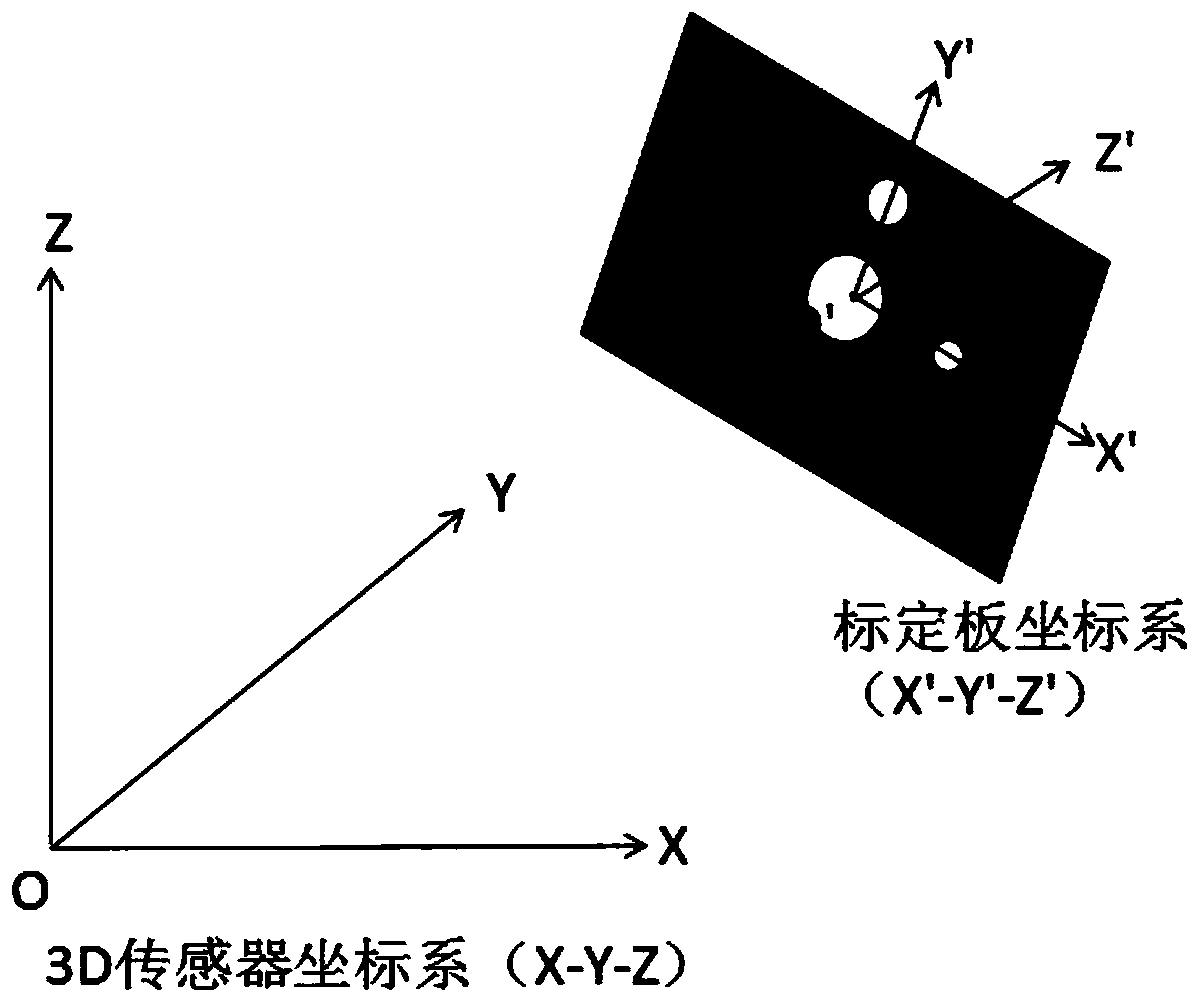
[0034] Such as figure 1 As shown, in this embodiment, a 3D structured light sensor and a six-degree-of-freedom industrial robot are taken as examples to illustrate the robot 3D vision hand-eye calibration method and based on the hand-eye calibration method, the position and posture of the workpiece under the 3D sensor are converted into the base coordinates of the robot. The specific realization of the position and attitude of the system.

[0035] The steps of the robot 3D vision hand-eye calibration method in this embodiment are as follows:

[0036] Step S1: set as figure 2 The shown calibration plate is installed on the robot flange, move the end of the robot actuator, change the position and attitude of the flange, and obtain the attitude of multipl...


PUM


Abstract

The invention discloses a robot 3D vision hand-eye calibration method. The method comprises the steps that S1, a posture, relative to robot base coordinates, of a robot flange and a posture, relativeto a 3D sensor coordinate system, of a calibration plate are obtained; S2, a rotation matrix, relative to a robot base coordinate system, of the 3D sensor coordinate system is calculated; S3, multiplecoordinate data of workpiece grasping points in the 3D sensor coordinate system and corresponding multiple coordinate data in the base coordinate system of a robot base are obtained; S4, transformational relations of X coordinate axes, Y coordinate axes and Z coordinate axes of the 3D sensor coordinate system and the robot base coordinate system are calculated. Compared with traditional hand-eyecalibration that only one transformational matrix is used for describing transform from the 3D sensor coordinate system to the robot base coordinate, by means of the robot 3D vision hand-eye calibration method, the transformational relations of positions and postures from a 3D sensor to the robot base coordinates are obtained respectively, compared with the prior art, the method is more flexible,the precision requirements in actual engineering application can be better met, and the hand-eye calibration precision is improved.

Description

technical field [0001] The invention belongs to the technical field of robot 3D vision calibration, and in particular relates to a robot 3D vision hand-eye calibration method. Background technique [0002] The rapid advancement of intelligent manufacturing has led to the rapid development of multi-joint robots. Industrial robots have participated in various fields of industrial manufacturing and production, and have become an indispensable role in the process of factory automation and intelligence. Machine vision endows robot eyes with advanced image processing, 3D data analysis algorithms, and the application of artificial intelligence technology, so that robot actions are no longer limited to point-to-point movements or established trajectories obtained through teaching, but under the guidance of vision For more flexible and intelligent actions, the application in high-precision detection and workpiece grasping and positioning is in the ascendant. Compared with traditiona...

Claims


Application Information

Patent Timeline
IPC IPC(8): B25J9/16B25J19/00G06T7/00
CPCB25J9/16B25J19/00G06T7/00
Inventor 付雨蒋鑫巍陈贵
Owner 苏州汉振深目智能科技有限公司
Learn More