Cylindrical battery cell film-making and winding machine

A cylindrical, winding machine technology, applied in the direction of cylindrical shell battery/battery, secondary battery manufacturing, circuit, etc., can solve the problems of short circuit detection time, too tight cell compaction, slow response of cylinder action, etc. Achieve the effect of improving the response speed, preventing the cell from falling, and ensuring continuity

Pending Publication Date: 2018-11-13
ZHUHAI HIGRAND ELECTRONICS TECH
View PDF0 Cites 7 Cited by
  • Summary
  • Abstract
  • Description
  • Claims
  • Application Information

AI Technical Summary

Problems solved by technology

However, the disadvantages of electric control such as cylinder drive are: the cylinder needs to cooperate with electrical components and electric control signals to operate, which makes the response of the cylinder slow and the response time is long, which is not conducive to improving the production efficiency of the rolling equipment.
However, the existing gluing equipment has the disadvantage of low production efficiency, because the gluing process is to first stick the first end of the tape on the outer circumferential surface of the rolled battery cell, and then drive the tape through the rotation of the rolling needle. Wrapped on the outer circumferential surface of the battery core, after the tape is wound to an appropriate length, the tape is cut and finished, so that the tape can only be cut after the glue is applied, which affects the overall time of glue application
Moreover, when the existing adhesive tape is wound, it is easy to exert additional pressure on the battery core, so that the inside of the battery core is easily compacted too tightly, which a

Method used


Image

  • Cylindrical battery cell film-making and winding machine
  • Cylindrical battery cell film-making and winding machine
  • Cylindrical battery cell film-making and winding machine

Examples


Embodiment Construction

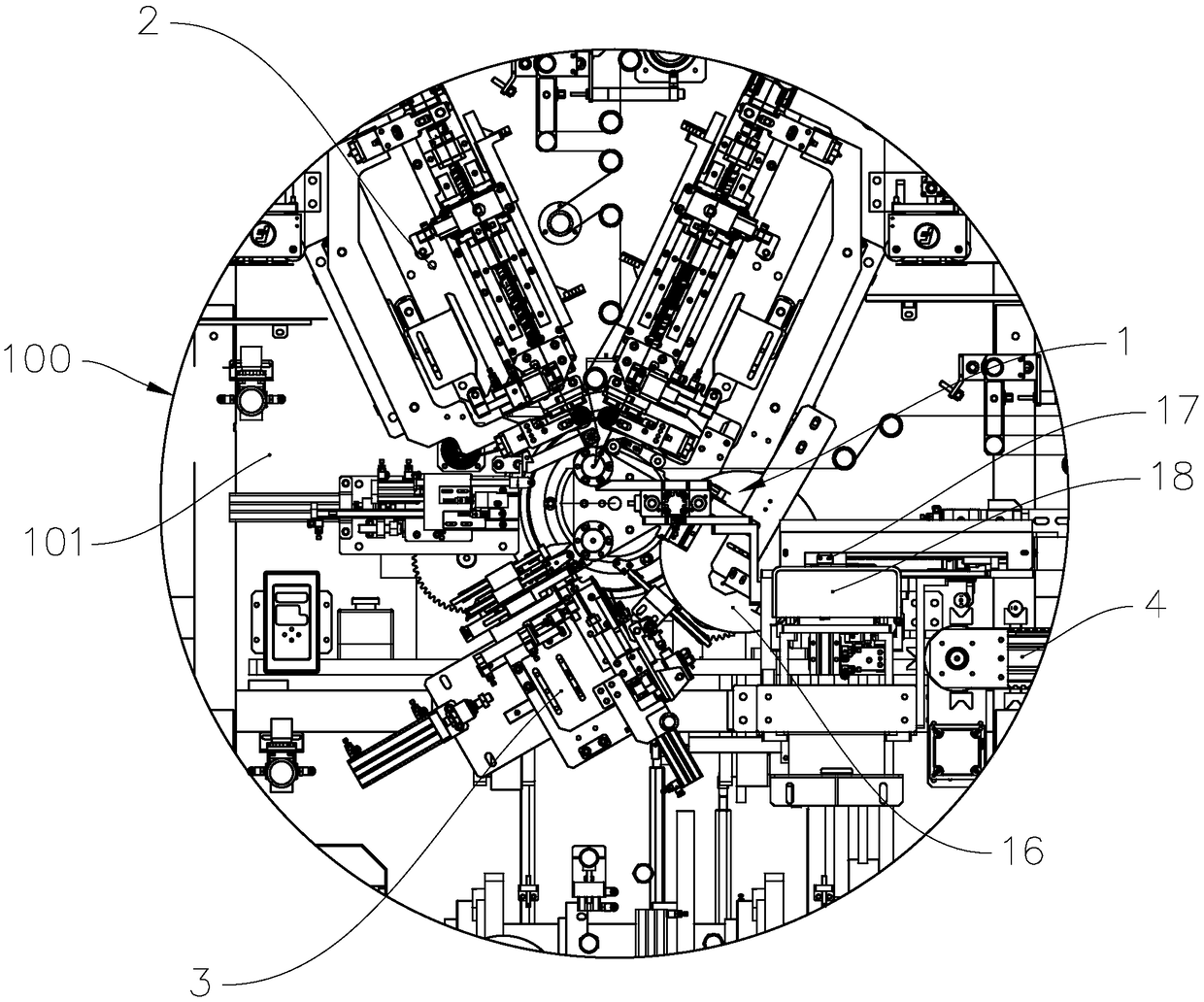
[0044] refer to Figure 1 to Figure 3 , the cylindrical battery sheet winding machine 100 includes a frame 101, a winding head device 1, a pole piece insertion cutting device 2, a gluing device 3 and a battery short circuit test device 4, wherein the pole piece insertion cutting device 2. The gluing device 3 , the cell short-circuit testing device 4 , and the winding head device 1 are all fixedly connected to the frame 101 .

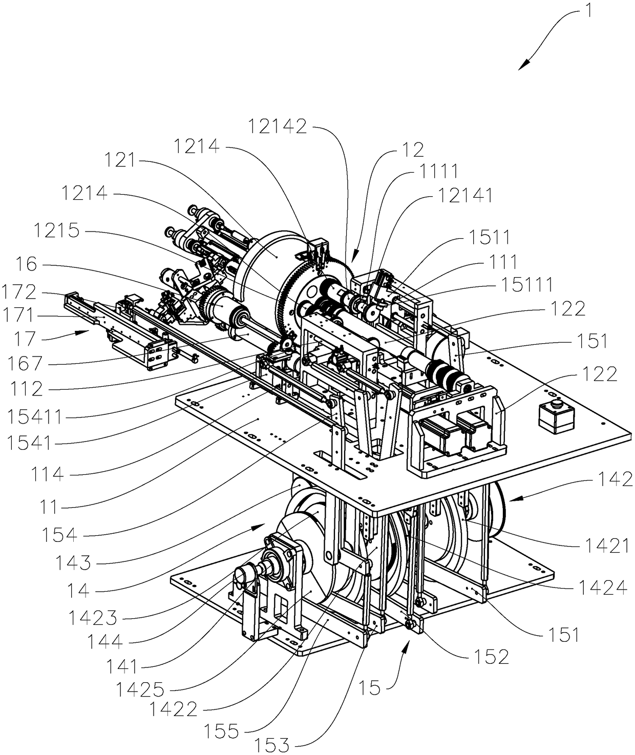
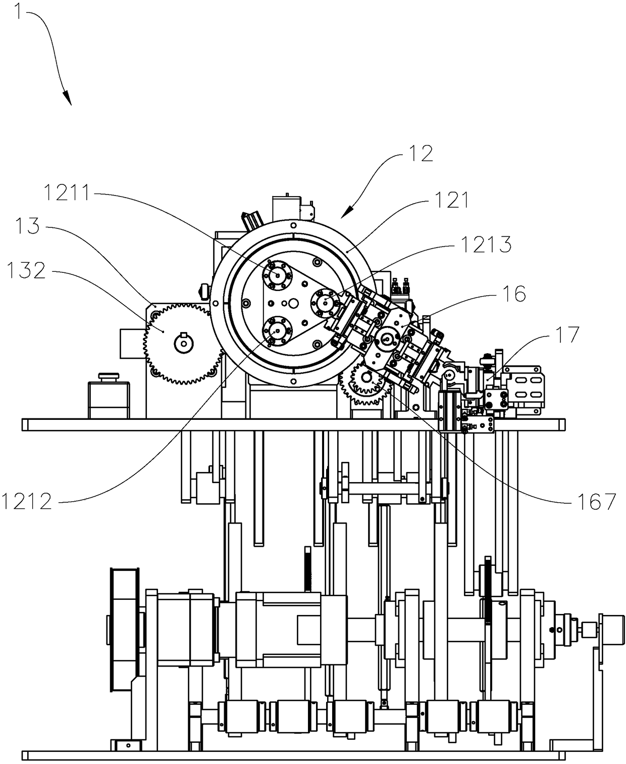
[0045] Specifically, the winding head device 1 includes a first mounting seat 11, a winding unit 12, a reversing unit 13, a first driving unit 14, a swing arm group unit 15, a cell blanking unit 16, and a cell moving unit 17. And hot hole unit 18. The first mounting base 11 is fixedly connected to the frame 101 . The winding unit 12 includes a winding head 121 and a drive mechanism 122, the winding head 121 is rotatably connected with the first mount 11 around its own axis, the winding head 121 includes a first station 1211, a second station 1212 and ...


PUM


Abstract

The invention provides a cylindrical battery cell film-making and winding machine, comprising a rack, and a winding head device, a pole piece inserting and cutting device, a diaphragm cut-off device and a gluing device which are connected with the rack, wherein the winding head device comprises a winding unit provided with a winding head, a first driving unit and a swing arm group unit; the winding head comprises a first station, a second station and a third station which are respectively provided with winding needles; each winding needle is provided with a first needle body and a second needle body; the first driving unit comprises a roller shaft as well as a first cam, a second cam and a third cam which are installed on the roller shaft; the swing arm group unit comprises a first swing arm group, a second swing arm group and a third swing arm group; the first cam drives the first swing arm group to control the first needle body of the first station to move along the axial direction of the winding head, the second cam drives the second swing arm group to control the first needle body of the third station to move along the axial direction of the winding head, and the third cam drives the third swing arm group to control the second needle body of the third station to move along the axial direction of the winding head. The cylindrical battery cell film-making and winding machinehas the advantages of being reliable in work, high in processing accuracy and rapid in production efficiency.

Description

technical field [0001] The invention relates to the technical field of battery production, in particular to a cylindrical battery sheet making and winding machine. Background technique [0002] The existing battery winding equipment is mainly used to install the positive electrode sheet, negative electrode sheet and separator in a certain order and then wind them into the battery cell, and to glue the rolled battery cell, short-circuit detection, etc. , which has the advantages of high production efficiency, low production cost and low rework rate of cell production. [0003] The conventional battery winding equipment is to roll the battery core through the winding head device, which mainly uses the winding head and the winding needle on it to cooperate with multiple independent cylinders to realize the rolling of the battery core and the battery after the glue is pasted. Core blanking and other operations, that is, through multiple independent cylinders to drive the windin...

Claims


Application Information

Patent Timeline
IPC IPC(8): H01M10/0587H01M10/04
CPCH01M10/0422H01M10/0587Y02E60/10Y02P70/50
Inventor 杨琪杨春超曹海霞刘秀娟
Owner ZHUHAI HIGRAND ELECTRONICS TECH
Why Eureka
Try Eureka