Protecting door for numerically controlled machine tool

A technology of CNC machine tools and protective doors, which is applied in the field of CNC machine tools, can solve problems such as blurred glass surfaces, collision damage between protective doors and fuselages, and increased noise, and achieve cumbersome replacement processes, easy disassembly and replacement, and scientific and reasonable structures Effect

Active Publication Date: 2018-11-13
青岛瑞莱堡精密工业有限公司
View PDF7 Cites 5 Cited by
  • Summary
  • Abstract
  • Description
  • Claims
  • Application Information

AI Technical Summary

Problems solved by technology

[0003] The invention provides a protective door for numerically controlled machine tools, which can effectively solve the problem that the protective door in the current market has a simple structure and after a long time of use, the friction force increases during the sliding process, causing the protective door to slide slowly and make noise when sliding. The increase is not conducive to the construction of a high-quality workshop environment. The water used for cooling is easy to adhere to the surface of the observation glass in the middle of the protective door, causing the glass surface to be blurred, so that observers cannot effectively observe the working status of the CNC machine tool through the observation glass, and it is difficult to timely Discovering unexpected conditions during the cutting process and stopping the CNC machine tool in time will cause damage to the cutting tool and the workpiece. In order to prevent the side wall of the protective door from directly colliding with the fuselage, rubber gaske...

Method used


Image

  • Protecting door for numerically controlled machine tool
  • Protecting door for numerically controlled machine tool
  • Protecting door for numerically controlled machine tool

Examples


Embodiment

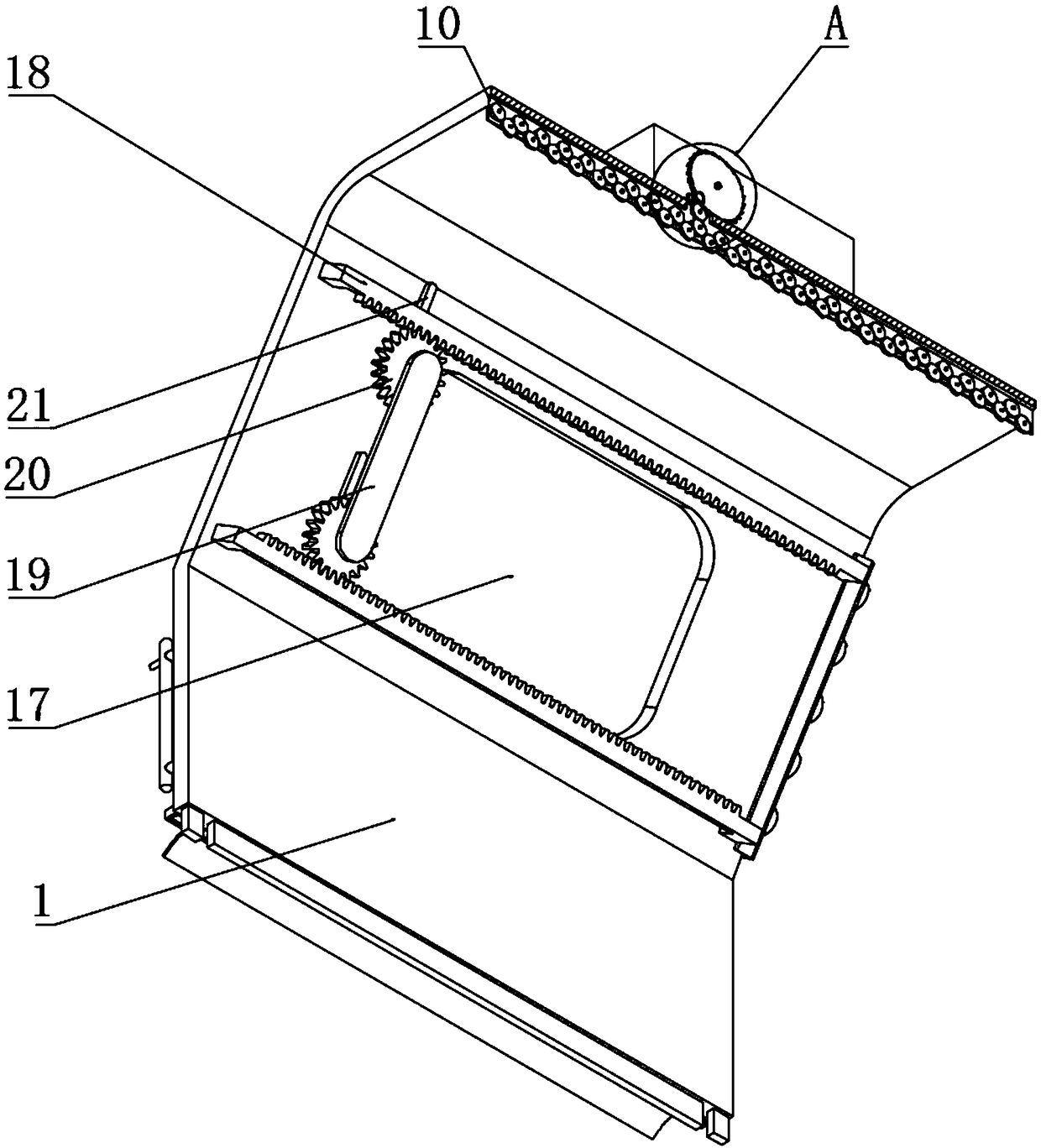
[0033] Example: such as Figure 1-8As shown, the present invention provides a technical solution, a protective door for numerically controlled machine tools, including a door body 1, and a lubricating oil tank 2 is installed on the top of the door body 1, in order to ensure the stability of the lubricating oil tank 2 after installation, and prevent the lubricating oil tank 2 from being arbitrarily Shaking, the top of the door body 1 is equipped with a limit baffle at the position corresponding to the outer side of the lubricating oil tank 2, the inside of the lubricating oil tank 2 is installed with an extrusion plate 3, the middle of the extrusion plate 3 is provided with an adjustment screw hole 4, and the middle of the adjustment screw hole 4 is installed with a screw 5. A ratchet mechanism 6 is installed on one side of the screw rod 5 outside the lubricating oil tank 2. The ratchet mechanism 6 includes a mounting plate 601, a mounting frame 602, an adjustment clamp 603 and ...


PUM


Abstract

The invention discloses a protecting door for a numerically controlled machine tool. The protecting door comprises a door body. A lubricating oil tank is mounted on the top of the door body, a connecting wheel is mounted in a connecting notch, an adjusting wheel is mounted below the connecting wheel, a moving wheel is mounted below the adjusting wheel, a movable gear is mounted on one side of theconnecting plate through a rotary shaft, and a cleaning brush is coaxially mounted below the moving gear. The protecting door disclosed by the invention is scientific and reasonable in structure and safe and convenient to use. Sliding friction of the protecting door which moves is converted into rolling friction through the moving wheel, so that resistance subjected to the protecting door when theprotecting door moves is reduced, and meanwhile, lubricating oil of the lubricating oil tank is discharged through a liquid outlet hole of a hollow shaft and is effectively adsorbed to the surfaces of the adjusting wheel and the moving wheel, so that the side face of the moving wheel is coated with lubricating oil all the way when the moving wheel slides, the friction force of the protecting doorwhich moves is smaller, and the protecting door is pushed conveniently. Meanwhile, noise generated when the moving wheel slides is reduced, so that a high quality workshop environment is constructedconveniently better.

Description

technical field [0001] The invention relates to the technical field of numerical control machine tools, in particular to a protective door for numerical control machine tools. Background technique [0002] CNC machine tool is the abbreviation of digital control machine tool. It is an automatic machine tool equipped with a program control system. It can make the machine tool move and process parts according to the programmed program. It integrates machinery, automation, computer, measurement, microelectronics, etc. The latest technology, compared with traditional machine tools, CNC machine tools have the advantages of high flexibility, high processing precision, stable and reliable processing quality, high productivity and improved working conditions. , column, beam, sliding seat, worktable, spindle box, feed mechanism, tool holder and automatic tool changer and other mechanical components, among which the protective door plays a certain role in the installation and protectio...

Claims


Application Information

Patent Timeline
IPC IPC(8): B23Q11/08B23Q11/12B23Q11/00
CPCB23Q11/0042B23Q11/08B23Q11/122
Inventor 张明明
Owner 青岛瑞莱堡精密工业有限公司
Why Eureka
Try Eureka