Bridge damage detection method
A damage detection and bridge technology, applied in the direction of measuring device, elasticity test, machine/structural component test, etc., can solve problems such as limited influence of overall characteristics, unsatisfactory structural effect, and infeasibility.
- Summary
- Abstract
- Description
- Claims
- Application Information
AI Technical Summary
Problems solved by technology
Method used
Image
Examples
Embodiment 1
[0125] For the damage detection method based on the influence line, the calculation and analysis of the numerical simulation dynamic response of the 2-axle vehicle crossing the bridge is carried out. The parameters of the vehicle model involved in the calculation are shown in Table 1:
[0126] Table 1. Vehicle parameters for numerical calculations
[0127]
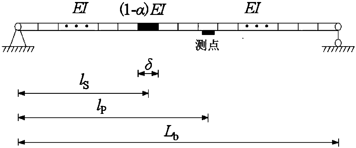
[0128] The main parameters of the simply supported girder bridge used in the numerical simulation include: bridge length L b =16m, bending stiffness EI=4.36×10⁹N·m2, linear density ρ=1.07×10⁴kg / m, damping ratio 0.02. Two damage situations are considered in the numerical simulation, single damage: l s =6.5m, δ=1m, α=0.2; two damages: l s1 = 7.5m and l s2 =11.5m, δ 1 = 1m, α 1 = 0.3, δ 2 = 1m, α 2 = 0.2. In order to ensure the accuracy of the numerical simulation, a lower average speed of 2m / s is adopted, and the influence of road irregularities is not considered at low speeds. Add a certain white noise signal to...
Embodiment 2
[0138] Model introduction
[0139] A laboratory model test is carried out to further verify the damage detection method based on the bridge influence line of the present invention. The test site layout is as follows Figure 10 , The test components include: bridge model, transverse baffle, loading vehicle, speed acquisition device, displacement sensor and dynamic signal testing instrument. The main girder of the bridge model consists of two independent steel girders, one is a three-span test girder, which is the upper span of 1.5m, the test span of 5m and the outgoing span of 1.5m, and artificial damage is caused on the test span. The other piece is an auxiliary beam, on which a smooth guide rail is fixed to support the "V" wheel of the loading vehicle, so that the "V" wheel of the test vehicle can move linearly along the direction of the guide rail. The two pieces of I-beams are independent of each other, and the lateral spacing of their centerlines is 0.258m, which is cons...
PUM
| Property | Measurement | Unit |
|---|---|---|
| Horizontal spacing | aaaaa | aaaaa |
Abstract
Description
Claims
Application Information
 - Generate Ideas
- Intellectual Property
- Life Sciences
- Materials
- Tech Scout
- Unparalleled Data Quality
- Higher Quality Content
- 60% Fewer Hallucinations
Browse by: Latest US Patents, China's latest patents, Technical Efficacy Thesaurus, Application Domain, Technology Topic, Popular Technical Reports.
© 2025 PatSnap. All rights reserved.Legal|Privacy policy|Modern Slavery Act Transparency Statement|Sitemap|About US| Contact US: help@patsnap.com


