
Multi-view-field medium-wave infrared optical system and view field switching method thereof

An infrared optical system and multi-field-of-view technology, applied in the field of forward-looking infrared imaging systems, can solve the problems of fleeting fighter jets, long zoom time, difficulty in ensuring focal length accuracy and optical axis consistency, and improve the signal-to-noise ratio. , the effect of low precision requirements

Active Publication Date: 2018-11-06
凯迈(洛阳)测控有限公司
View PDF7 Cites 4 Cited by
  • Summary
  • Abstract
  • Description
  • Claims
  • Application Information

AI Technical Summary

Problems solved by technology

However, the structure of the continuous zoom system is complex, difficult to install and adjust, and it is difficult to guarantee the accuracy of the focal length and the consistency of the optical axis during the zooming process.
In addition, the zoom time of continuous zoom is long, currently about 6s
However, the situation on the battlefield is changing rapidly, and fighters are fleeting, so too long a field of view switching time will delay fighters

Method used


Image

  • Multi-view-field medium-wave infrared optical system and view field switching method thereof
  • Multi-view-field medium-wave infrared optical system and view field switching method thereof
  • Multi-view-field medium-wave infrared optical system and view field switching method thereof

Examples


Embodiment Construction

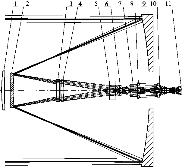
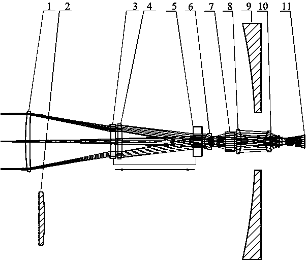
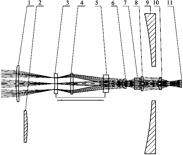
[0033] Such as Figure 1 to Figure 13 As shown, a kind of multi-field-of-view mid-wave infrared optical system of the present invention comprises a first meniscus-shaped positive lens 1, a secondary reflector 2, a first Biconcave negative lens 3, first biconvex positive lens 4, first meniscus negative lens 5, second meniscus negative lens 6, second biconcave negative lens 7, second biconvex positive lens 8, primary reflection Mirror 9, second meniscus positive lens 10 and imaging surface 11.

[0034] The mirror surface of the main reflector 9 is set towards the object side, and is used to reflect the natural light reflected from the object side to the secondary reflector 2 in the telephoto imaging mode of the present invention, and then the light is reflected by the secondary reflector 2 in sequence Through the first biconcave negative lens 3, the first biconvex positive lens 4, the first meniscus negative lens 5, the second meniscus negative lens 6, the second biconcave nega...


PUM


Abstract

The invention relates to the field of forward-looking infrared imaging systems, in particular to a multi-view-field medium-wave infrared optical system and a view field switching method thereof. The system is composed of a first meniscus positive lens, a secondary reflecting mirror, a first double-concave negative lens, a first double-convex positive lens, a first meniscus negative lens, a secondmeniscus negative lens, a second double-concave positive lens, a second double-convex negative lens, a main reflecting mirror, a second meniscus positive lens, and an imaging plane that are distributed at the optical axis successively and coaxially from an object side to an image side. The system has a simple structure; the view field switching time is short and is controlled to be within 1s; theimaging quality is high; the optical axis consistency during the view field switching process can reach one pixel; and compared with the existing single-view-field and continuous zoom infrared opticalsystems, the multi-view-field medium-wave infrared optical system is simple and practical.

Description

technical field [0001] The invention relates to the field of forward-looking infrared imaging systems, in particular to a multi-field mid-wave infrared optical system and a field-of-view switching method. Background technique [0002] Since the forward-looking infrared (FLIR) imaging system is passive detection, it has the characteristics of good concealment and strong anti-electronic interference, and can quickly obtain target information in the covered airspace. It has been widely used in guidance, monitoring, target detection and tracking, etc. field. [0003] In the forward-looking infrared system, the infrared optical system is the first link to obtain target information. The infrared optical system is divided into single-field, multi-field, and continuous zoom. Due to the single function of the single-field infrared optical system, the actual use is limited, and it is difficult to meet the development needs of modern infrared optical systems. The advantage of the con...

Claims


Application Information

Patent Timeline
IPC IPC(8): G02B17/08G02B17/00
CPCG02B17/004G02B17/0804
Inventor 吴海清李同海赵新亮谈大伟李泽宇
Owner 凯迈(洛阳)测控有限公司
Learn More