
Distributed optical fiber multi-parameter pipeline leakage positioning and warning system and leakage positioning method

A distributed optical fiber and pipeline leakage technology, which is applied in the pipeline system, gas/liquid distribution and storage, mechanical equipment, etc., can solve the problems of crude oil pipeline leakage monitoring, leakage point location, leakage location method, etc., to reduce false alarm rate , Improve positioning accuracy and leakage alarm speed, and improve the effect of accuracy

Inactive Publication Date: 2018-11-06
青岛汇安谷科技发展有限公司
View PDF17 Cites 14 Cited by
  • Summary
  • Abstract
  • Description
  • Claims
  • Application Information

AI Technical Summary

Problems solved by technology

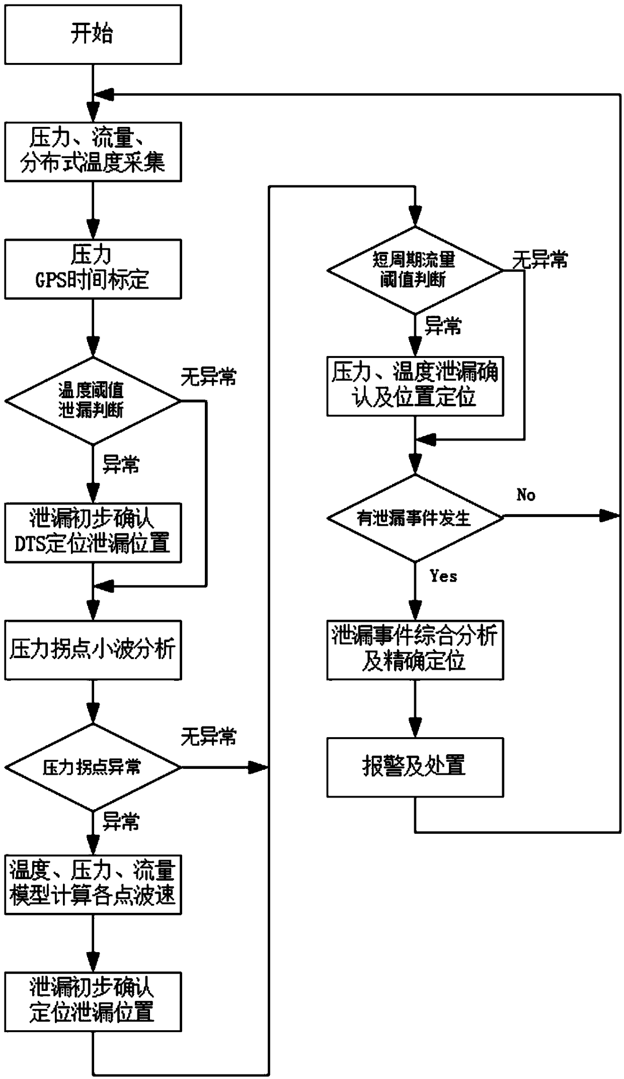
[0004] In order to solve the above technical problems, the present invention provides a distributed optical fiber multi-parameter pipeline leakage location alarm system and a leakage location method. The defects of negative pressure wave leakage monitoring system, infrasonic wave leakage monitoring system and distributed optical fiber temperature leakage monitoring system have comprehensively solved the problems of crude oil pipeline leakage monitoring and leakage point location

Method used


Image

  • Distributed optical fiber multi-parameter pipeline leakage positioning and warning system and leakage positioning method
  • Distributed optical fiber multi-parameter pipeline leakage positioning and warning system and leakage positioning method
  • Distributed optical fiber multi-parameter pipeline leakage positioning and warning system and leakage positioning method

Examples


Embodiment Construction

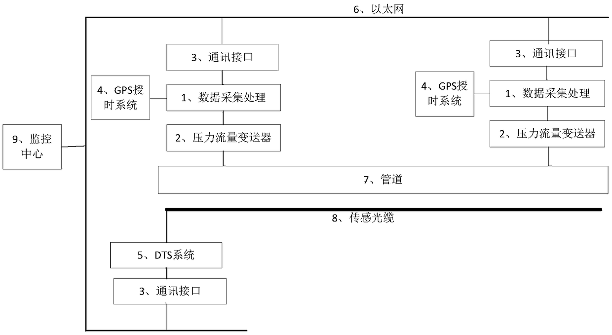
[0028] Such as figure 1 As shown, the distributed optical fiber multi-parameter pipeline leakage location alarm system includes a sensing optical fiber 8 laid in the same ditch as the pipeline, a DTS system 5 connected to the sensing optical fiber 8, and at least two sets of negative pressure waves are arranged on the pipeline 7. The monitoring device, the negative pressure wave monitoring system and the DTS system 5 are all connected to the monitoring center 9 through the network, the negative pressure wave monitoring device includes the pressure flow transmitter 2 connected with the pipeline 7, the pressure flow transmitter 2 and the The data collector 1 is connected, and the data collector 1 is connected with a GPS timing system. The network is preferably Ethernet 6, which is a wired data communication network. Both the data collector 1 and the DTS system 5 are connected to the Ethernet 6 through the communication interface 3; the communication interface 3 is a protocol co...


PUM


Abstract

The invention relates to a distributed optical fiber multi-parameter pipeline leakage positioning and warning system and a leakage positioning method. The distributed optical fiber multi-parameter pipeline leakage positioning and warning system comprises a sensing optical fiber laid in the same ditch as a pipeline and a DTS system connected with the sensing optical fiber. At least two negative-pressure wave monitoring devices are arranged on the pipeline. A negative-pressure wave monitoring system and the DTS system are both connected with a monitoring center through communication interfaces and the Ethernet network. Each negative-pressure wave monitoring device comprises a pressure flow transmitter connected with the pipeline, and the pressure flow transmitter is connected with a data acquisition unit. The data acquisition units are connected with GPS timing antennas. The distributed optical fiber multi-parameter pipeline leakage positioning and warning system has the beneficial effects that the defects that a negative-pressure wave monitoring and infrasonic wave leakage monitoring system cannot conduct monitoring and cannot conduct accurate positioning due to small leakage and adistributed optical fiber temperature leakage monitoring system cannot monitor leakage due to a low-temperature difference are overcome; based on the temperatures, obtained by a distributed optical fiber temperature measuring system, of all points, the wave velocity is calculated and corrected accurately, and accurate positioning of the leakage position is achieved.

Description

technical field [0001] The invention belongs to the technical field of pipeline monitoring, in particular to a distributed optical fiber multi-parameter pipeline leakage location alarm system and a leakage location method. Background technique [0002] Pipeline transportation has unique advantages in crude oil transportation, and has become the fifth largest means of transportation after railways, highways, waterways, and air transportation. Due to inevitable aging, corrosion, drilling and oil theft, pipeline leakage occurs from time to time , seriously interfered with normal production, resulting in huge economic losses and environmental pollution. Therefore, the pipeline leakage detection and positioning system is of great practical significance for timely detection of pipeline leakage, combating oil theft, protecting the environment and reducing economic losses. [0003] At present, the leakage monitoring and leakage location technologies of crude oil pipeline mainly inc...

Claims


Application Information

Patent Timeline
IPC IPC(8): F17D5/02F17D5/00
CPCF17D5/00F17D5/02
Inventor 徐成山蒋能记李洪福王晓程周素芹魏茂安
Owner 青岛汇安谷科技发展有限公司
Learn More