CAN bus engine monitor and control method thereof
A CAN bus and control method technology, applied in the direction of combustion engine, engine components, engine starting, etc., can solve problems such as inability to control engine start, engine damage, etc., and achieve easy operation, high installation flexibility, and high integration. Effect
- Summary
- Abstract
- Description
- Claims
- Application Information
AI Technical Summary
Problems solved by technology
Method used
Image
Examples
Embodiment 1
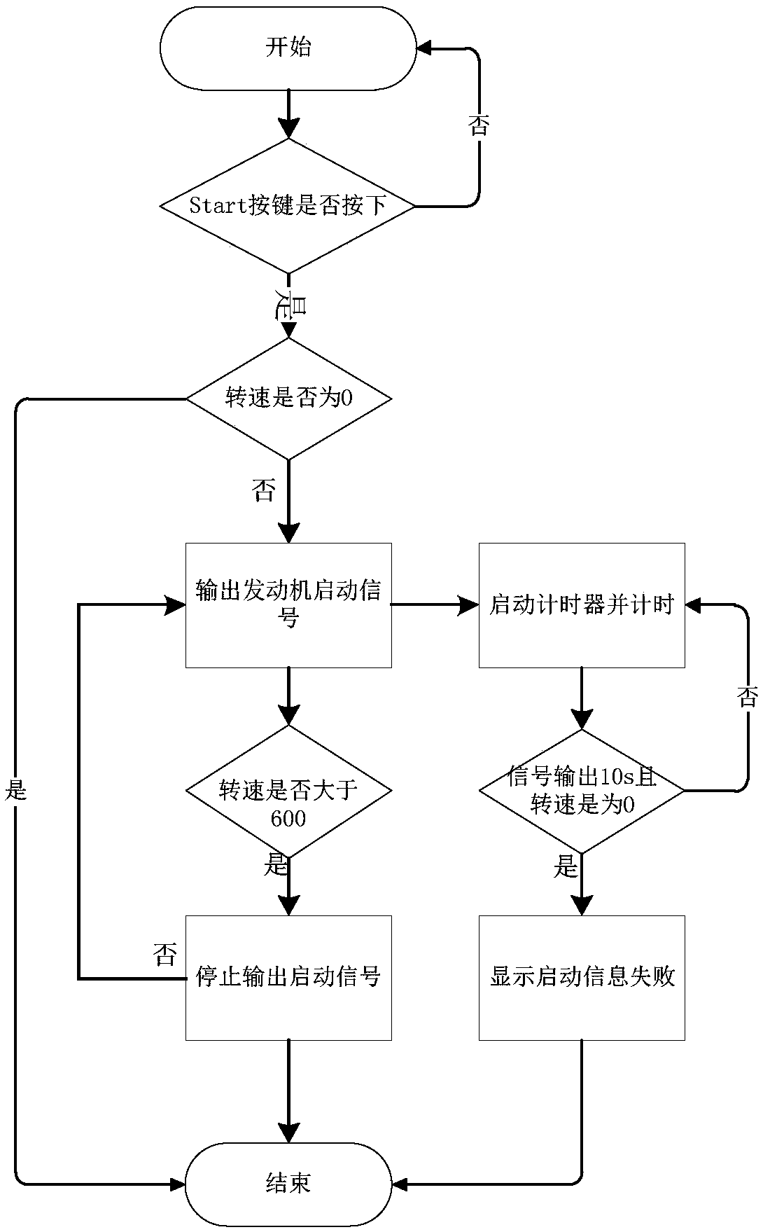
[0051] Such as figure 1 As shown, the present embodiment provides a CAN bus engine monitor, including a key operation module, a display module, an output module, a CAN communication module, a storage module and an MCU control module;
[0052] Key operation module: responsible for inputting relevant instructions of engine operation to the MCU control module, the key operation module includes a knob for adjusting the engine speed and a key for starting and stopping the engine;
[0053] Display module: responsible for displaying relevant data information of engine operation;
[0054] Output module: responsible for outputting control signals to the engine for controlling the start and stop of the engine;
[0055] CAN communication module: responsible for receiving commands from the MCU control module to communicate with the engine, sending relevant commands to the engine, and collecting relevant data information on engine operation and sending them to the MCU control module;
[...
Embodiment 2
[0073] This embodiment is further optimized on the basis of Embodiment 1, specifically:
[0074] Such as Figure 5 Shown is the main body of the engine monitor of this embodiment, as Figure 6 As shown, the main body of the engine monitor includes a knob 1, a silicone button 2, a pcb button 3, a face shell 4, a lens 5, a liquid crystal screen 6, a screen fixing frame 7, a pcb main board 8, a pcb connector 9, a waterproof ring 10, Waterproof plug 11, bottom shell 12, shock absorbing pad 13, fixed frame 14 and fixing screw 15, described silicone button 2 and pcb button 3 are adapted, and cover is connected outside pcb button 3, convenient button operation, improve operating personnel Comfortable keys, and also dustproof and waterproof;
[0075] Described display module, output module, CAN communication module, storage module and MCU control module are all welded on the pcb mainboard 8 by soldering, and described button operation module comprises the start-stop control module a...
Embodiment 3
[0084] This embodiment is further optimized on the basis of Embodiment 2, specifically:
[0085] Such as Figure 8 As shown, the display module includes a model AT89C51 single-chip microcomputer U1 and a liquid crystal screen LCD connected with the single-chip microcomputer U1, and the data bits D0-D7 of the liquid crystal screen LCD are respectively connected with P1.0-P1.7 of the single-chip microcomputer U1;
[0086] The RS position, the RW position and the E position of the liquid crystal screen LCD are respectively connected with the P2.0 / A8 position, the P2.1 / A9 position and the P2.2 / A10 position of the single-chip microcomputer U1, and are controlled by the single-chip microcomputer U1. To work, a crystal oscillator X2 is connected between the XTAL1 position and the XTAL2 position of the single-chip microcomputer U1, the two ends of the crystal oscillator X2 are respectively connected to a capacitor C5 and a capacitor C6, and the other ends of the capacitor C5 and the c...
PUM
 Abstract
Description
Claims
Application Information
 - R&D Engineer
- R&D Manager
- IP Professional
- Industry Leading Data Capabilities
- Powerful AI technology
- Patent DNA Extraction
Browse by: Latest US Patents, China's latest patents, Technical Efficacy Thesaurus, Application Domain, Technology Topic, Popular Technical Reports.
© 2024 PatSnap. All rights reserved.Legal|Privacy policy|Modern Slavery Act Transparency Statement|Sitemap|About US| Contact US: help@patsnap.com


