Oily sludge cleaning method
A technology of oil sludge and cleaning agent, which is applied in chemical instruments and methods, sludge treatment, water/sludge/sewage treatment, etc., and can solve the problems of low degree of automation, high work intensity of operators, and low efficiency
- Summary
- Abstract
- Description
- Claims
- Application Information
AI Technical Summary
Problems solved by technology
Method used
Image
Examples
Embodiment 1
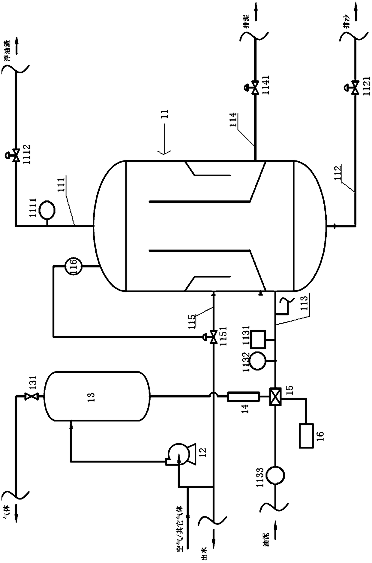
[0045] A micro-nano bubble oil sludge cleaning integrated device, its structure is as follows figure 1 As shown: it includes a cyclone cleaning separation tank 11, a dissolved air pump 12, a stabilization tank 13, a micro-nano bubble release device 14, a cleaning agent adding device 16 and a mixing device 15; the top of the cyclone cleaning separation tank 11 is provided with a floating oil pipe 111, the bottom end of the cyclone cleaning and separation tank 11 is provided with a sand discharge pipe 112, and the side wall of the cyclone cleaning and separation tank 11 is provided with an oil inlet pipe 113, a mud discharge pipe 114 and a drain pipe 115. The dissolved air pump 12 is communicated with the drain pipe 115, and the dissolved air pump 12, the stabilization tank 13 and the micro-nano bubble release device 14 are connected in sequence; the mixing device 15 is arranged on the oil inlet pipe 113 Above; the micronanobubble release device 14 and the cleaning agent adding ...
Embodiment 2
[0048] A sludge cleaning system for non-open air, its structure is as follows figure 2 Shown: including sludge pump 2, filter 3, homogenizing tank 4, screw pump 5, micro-nano bubble sludge cleaning integrated device 1 of the above-mentioned embodiment 1, oil-water separator 101, two-phase centrifuge 103 and sewage advanced treatment device 100; the sludge pump 2, the filter 3, the homogenizing tank 4 and the screw pump 5 are connected in sequence, the screw pump 5 is connected to the sludge inlet pipe 113, and the oil-water separator 101 communicates with the floating oil discharge pipe 111 , the two-phase centrifuge 103 communicates with the mud discharge pipe 114 , and the sewage advanced treatment device 100 communicates with the drain pipe 115 . The oil-water separator 101 is also connected with the dirty oil collection tank 102, the two-phase centrifuge 103 is also connected with the harmless treatment device 104, and the homogenization tank 4 is also equipped with a hea...
Embodiment 3
[0050] A sludge cleaning system for open air, its structure is as follows image 3 Shown: includes a crusher 7, a tempering tank 8, a vibrating screen 9, a homogenizing tank 4, a screw pump 5, the micro-nano bubble sludge cleaning integrated device 1 of the above-mentioned embodiment 1, an oil-water separator 101, and a two-phase centrifuge 103 and sewage advanced treatment device 100; the crusher 7, the tempering tank 8, the vibrating screen 9, the homogenizing tank 4 and the screw pump 5 are connected in sequence, and the screw pump 5 is also connected with the screw pump The oil sludge inlet pipe 113 is connected, the oil-water separator 101 is connected with the oil floating pipe 111, the two-phase centrifuge 103 is connected with the mud discharge pipe 114, and the advanced sewage treatment device 100 is connected with the The drain pipe 115 is connected; the oil-water separator 101 is also connected with the dirty oil collection tank 102, the two-phase centrifuge 103 is ...
PUM
| Property | Measurement | Unit |
|---|---|---|
| particle diameter | aaaaa | aaaaa |
Abstract
Description
Claims
Application Information
 - R&D
- Intellectual Property
- Life Sciences
- Materials
- Tech Scout
- Unparalleled Data Quality
- Higher Quality Content
- 60% Fewer Hallucinations
Browse by: Latest US Patents, China's latest patents, Technical Efficacy Thesaurus, Application Domain, Technology Topic, Popular Technical Reports.
© 2025 PatSnap. All rights reserved.Legal|Privacy policy|Modern Slavery Act Transparency Statement|Sitemap|About US| Contact US: help@patsnap.com


