A three-dimensional positioning device for installing an automobile air duct

A positioning device, three-dimensional technology, applied in auxiliary devices, workpiece clamping devices, auxiliary welding equipment, etc., can solve the problem of inaccurate positioning and installation, defects in the wedge process, inability to ensure uniform force on the workpiece, loose installation of air ducts, etc. question

Active Publication Date: 2020-11-13
芜湖众梦电子科技有限公司
View PDF6 Cites 0 Cited by
  • Summary
  • Abstract
  • Description
  • Claims
  • Application Information

AI Technical Summary

Problems solved by technology

[0006] (1) The clamping and positioning device of the existing three-dimensional positioning device installed on the automobile air duct cannot meet the requirement of applying equal pressure to the positioning fixture on the surroundings of the installation workpiece sleeve during the clamping process, and cannot ensure that the workpiece is evenly stressed and thus affects the installation of the workpiece The sleeve is positioned smoothly, resulting in inaccurate positioning and flaws in the wedging process of installation
[0007] (2) Most of the existing three-dimensional positioning devices installed in automobile air ducts are driven by humans, and there are also cylinders or hydraulic cylinders used to drive the positioning process, but the linkage rods installed in the cylinders or hydraulic cylinders may appear slightly Deviation, this deviation may lead to loose air duct installation, unstable installation and other conditions

Method used


Image

  • A three-dimensional positioning device for installing an automobile air duct
  • A three-dimensional positioning device for installing an automobile air duct
  • A three-dimensional positioning device for installing an automobile air duct

Examples


Embodiment Construction

[0037] The following will clearly and completely describe the technical solutions in the embodiments of the present invention with reference to the accompanying drawings in the embodiments of the present invention. Obviously, the described embodiments are only some, not all, embodiments of the present invention. Based on the embodiments of the present invention, all other embodiments obtained by persons of ordinary skill in the art without making creative efforts belong to the protection scope of the present invention.

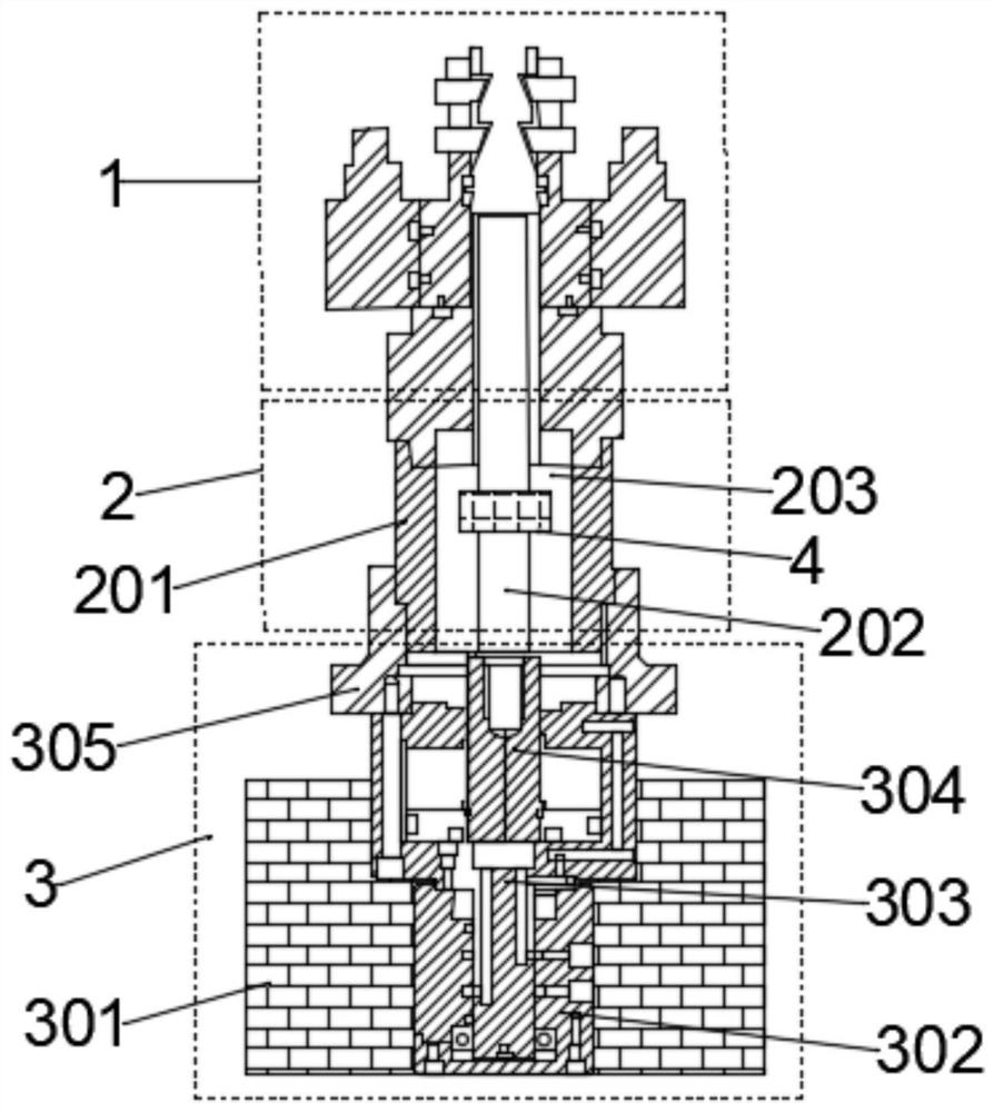
[0038] like figure 1 As shown, the present invention provides a kind of three-dimensional positioning device for the installation of automobile air ducts, including a positioning head 1, the lower end of the positioning head 1 is connected with a positioning head control assembly 2, and the lower end of the positioning head control assembly 2 is connected There is a power assembly 3, and the inside of the chamber of the positioning head control assembly 2 is p...


PUM


Abstract

The invention discloses a three-dimensional positioning device for installation of an automobile air pipe. The three-dimensional positioning device comprises a positioning head, the lower end of the positioning head is connected with a positioning head control assembly, and the lower end of the positioning head control assembly is connected with a power assembly; a deviation correcting guide sleeve is arranged in a cavity of the positioning head control assembly, and an air pipe installation workpiece sleeve is fixedly arranged at the top end of the positioning head. In the whole installationand sleeving process, an expansion cavity in the positioning head is used for expanding and retracting, so that positioning of a workpiece is achieved. The designed expansion cavity is a completely symmetric cavity, so that the positioning extrusion force borne by the air pipe installation workpiece sleeve at the same time is completely the same, the stability of the workpiece in the positioning process is guaranteed, and the situation that the workpiece is damaged is avoided. The deviation correcting guide sleeve utilizes the advantages that a closed-loop system is fast in response and high in self-control capacity, and the characteristic that a closed-loop feedback system is matched with electromagnetic conversion is utilized, so that the situation that a coil group self-adjusts the deflection of a metal power connecting rod is achieved, and the precision of workpiece positioning is greatly improved.

Description

technical field [0001] The invention relates to the technical field of installing an automobile air duct, in particular to a three-dimensional positioning device for installing an automobile air duct. Background technique [0002] The mounting bracket of the automobile air duct is used to install and fix the parts of the automobile air duct. The air duct needs to be installed on this part. Sophisticated process. If there is an inclination in the process of connecting the air duct, it is easy to cause the air duct to leak, resulting in poor sealing of the air duct and even causing danger. Most of the current automobile air duct socketing process adopts a semi-automatic socketing method, and artificial pressure is applied to position the pipe sleeve for air pipe socketing. It is inevitable that artificial pressure is not uniform in the whole process, and the accuracy of the positioning process is also very low. The traditional top pressure positioning or clamping positioning...

Claims


Application Information

Patent Timeline
Patent Type & Authority Patents(China)
IPC IPC(8): B23K37/053B25B11/00
CPCB23K37/053B23K37/0531B25B11/00
Inventor 张阳姚晓峰李龙
Owner 芜湖众梦电子科技有限公司
Why Eureka
Try Eureka