Pipe cutter lifting device and pipe sizing cutting machine

A lifting device and pipe cutter technology, applied in auxiliary devices, welding/cutting auxiliary equipment, plasma welding equipment, etc., can solve problems such as inaccurate positioning

Pending Publication Date: 2018-11-06
ZHEJIANG INT MARITIME COLLEGE
View PDF1 Cites 2 Cited by
  • Summary
  • Abstract
  • Description
  • Claims
  • Application Information

AI Technical Summary

Problems solved by technology

[0004] In order to solve the problem of inaccurate positioning of the cutting equipment during the cutting process, the invention provides a tube cutter lifting device and a tube cutting machine

Method used


Image

  • Pipe cutter lifting device and pipe sizing cutting machine
  • Pipe cutter lifting device and pipe sizing cutting machine
  • Pipe cutter lifting device and pipe sizing cutting machine

Examples


Embodiment Construction

[0022] Below in conjunction with accompanying drawing and embodiment the present invention will be further described:

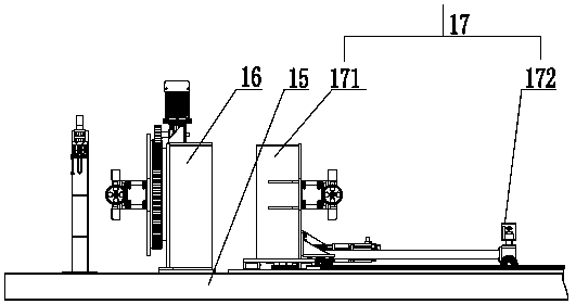
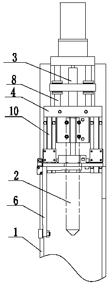
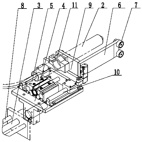
[0023] In the example, such as figure 1 , figure 2 , image 3 , Figure 4 As shown, the pipe cutter lifting device includes a fixed frame 1 and a cutter 2. The fixed frame 1 is provided with a No. 1 power device 3 that drives the cutter 2 to move up and down. The No. 1 power device 3 is connected to a No. 1 installation frame 4, the No. 1 mounting frame 4 is provided with a No. 2 power device 5, and the No. 2 power device 5 is connected to the cutter 2, and the No. 1 mounting frame 4 is provided with a limit stop parallel to the cutter 2 Article 6. The No. 1 power unit 3 and the No. 2 power unit 5 can be the No. 1 cylinder and the No. 2 cylinder. The No. 1 cylinder pushes the cutter 2 down, and then the cutter 2 is driven to the steel pipe by the No. 2 cylinder. The limit bar 6 can be Prevent the No. 2 cylinder from colliding with the steel pipe when dr...


PUM


Abstract

The invention discloses a pipe cutter lifting device and a pipe sizing cutting machine to solve the problem that locating is inaccurate in the cutting process of cutting equipment. The pipe cutter lifting device is characterized by comprising a fixing frame and a cutter. The fixing frame is provided with a first power device which drives the cutter to move up and down. The first power device is connected with a first installing frame. The first installing frame is provided with a second power device which is connected with the cutter. The first installing frame is provided with a limiting block strip parallel to the cutter. According to the pipe cutter lifting device, at first, the first power device drives the cutter to descend, then the second power device drives the cutter to a steel pipe, the limiting block strip can prevent the situation that when driving the cutter, the second power device collides with the steel pipe, and damage to the cutter is caused, when cutting is completed, the second power device is reset, and by arranging the second power device to drive the distance of the cutter, the steel pipe can be accurately located and cut.

Description

technical field [0001] The invention relates to the technical field of steel pipe cutting devices, in particular to a pipe cutter lifting device and a pipe cutting machine to a fixed length. Background technique [0002] At present, the cut-to-length steel pipes with large diameter, large wall thickness and long size are mostly completed by metal cutting process equipment, mainly by lathes and sawing machines; the current method of lathe processing is to pass the steel pipe through the core hole of the main shaft, and add Because of the diameter of the steel pipe, the numerically controlled feeder is installed as a specially designed lathe without exception. When the wall thickness of the steel pipe is large, cutting is difficult; when processing with a sawing machine, the processing speed is slow and the cost of consumables is high. [0003] In order to solve the deficiencies in the prior art, the patent application publication number CN106216823A has announced a two-way sy...

Claims


Application Information

Patent Timeline
Patent Type & Authority Applications(China)
IPC IPC(8): B23K10/00B23K37/02
CPCB23K10/00B23K37/02
Inventor 徐明伟汪益兵
Owner ZHEJIANG INT MARITIME COLLEGE
Why Eureka
Try Eureka