
Auto parts maintenance machine

A technology for auto parts and maintenance machines, applied in cleaning methods and tools, chemical instruments and methods, cleaning methods using tools, etc., can solve the problem of inability to limit the position of the hub, the inability to clean the groove of the support column of the hub, and the impossibility of cleaning debris at one time Eliminate the problems of permanent cleaning and other problems, and achieve the effect of good cleaning effect

Inactive Publication Date: 2020-06-05
NINGBO UNIVERSITY OF TECHNOLOGY
View PDF6 Cites 0 Cited by
  • Summary
  • Abstract
  • Description
  • Claims
  • Application Information

AI Technical Summary

Problems solved by technology

[0004] In order to solve the above-mentioned problems, the present invention provides an auto parts maintenance machine, which can solve the existing problems that the wheel hub cannot be limited, the sundries on the inner and outer walls of the wheel hub cannot be cleaned at one time, and the wheel hub cannot be cleaned at one time. The cleaning effect of the outer protrusions is poor, the grooves on the hub support columns cannot be cleaned, and the sundries cleaned from the hubs cannot be automatically separated and removed, etc.; it can realize stable limit fixation of the car hubs and comprehensive cleaning of the hubs , The function of removing the cleaned sundries can limit the position of the hub, clean the sundries on the inner and outer walls of the hub at one time, the protrusions on the outer side of the hub have a good cleaning effect, and the grooves on the support column of the hub can be cleaned Cleaning, automatic separation and removal of sundries from wheel hub cleaning, etc.

Method used


Image

  • Auto parts maintenance machine
  • Auto parts maintenance machine
  • Auto parts maintenance machine

Examples


Embodiment Construction

[0027] In order to make the technical means, creative features, goals and effects achieved by the present invention easy to understand, the present invention will be further described below in conjunction with specific illustrations. It should be noted that, in the case of no conflict, the embodiments in the present application and the features in the embodiments can be combined with each other.

[0028] Such as Image 6 As shown, there is a hub central groove in the middle of the hub, and five bolt holes are symmetrically arranged on the outside of the central groove, and five hub support columns are symmetrically arranged in the middle of the hub, and the positions of the five hub support columns are the same as those of the five bolts. The positions of the holes are arranged in a staggered manner, and square grooves are arranged on each hub support column.

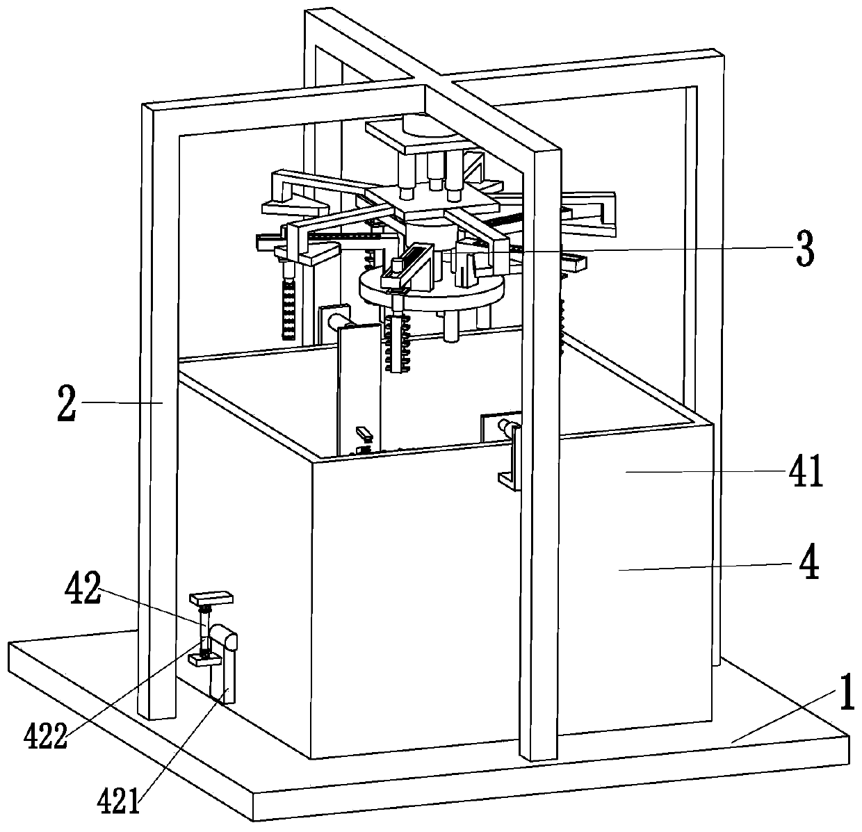
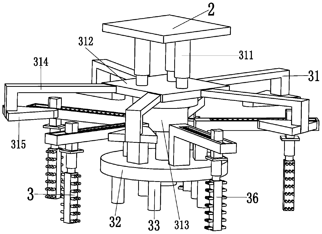
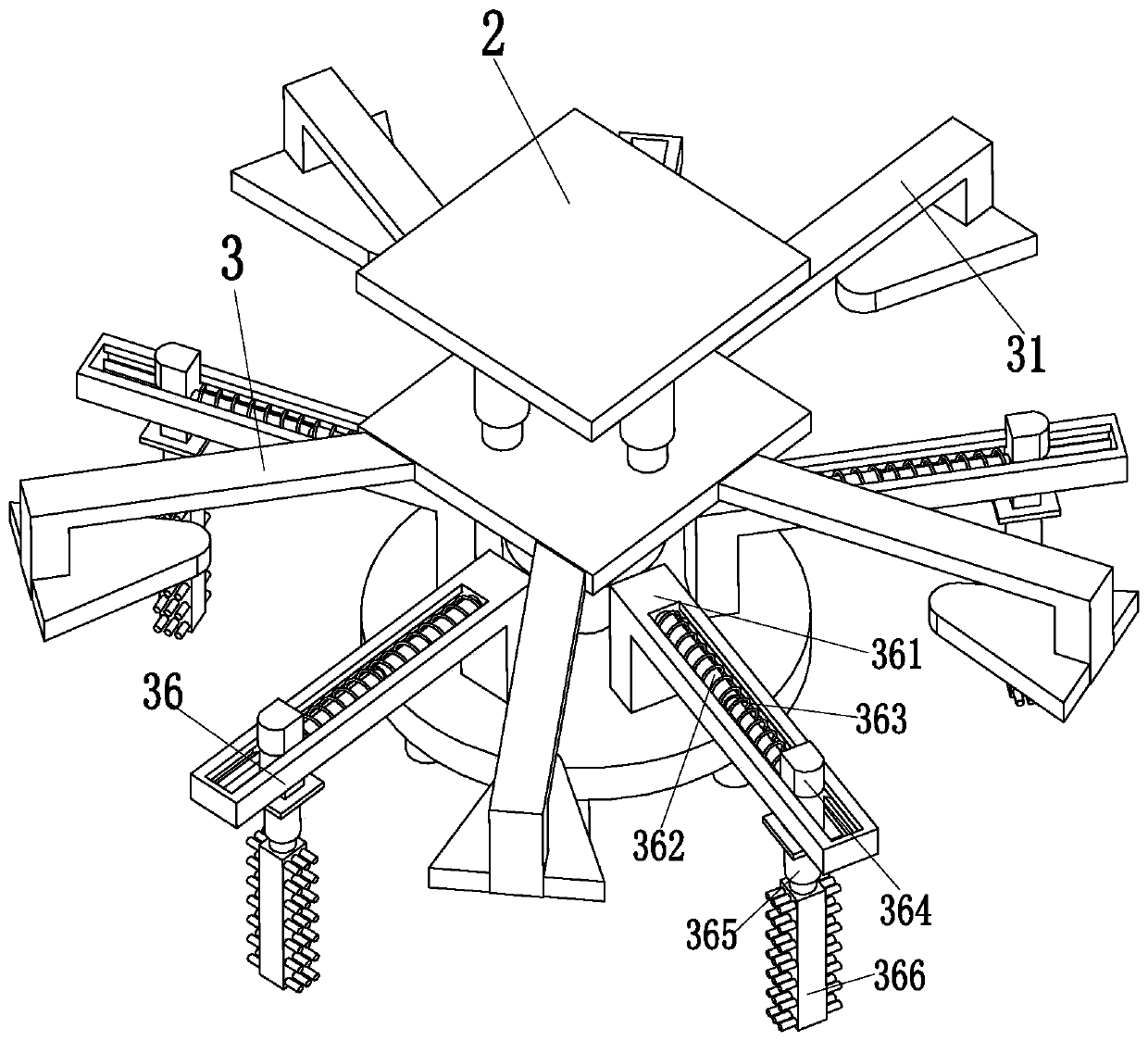
[0029] Such as Figure 1 to Figure 5 As shown, a kind of auto parts maintenance machine includes a supporting base 1...


PUM


Abstract

The invention relates to an auto part maintenance machine which comprises a supporting bottom plate, a supporting connecting rack, a fixing device and a cleaning device, wherein the supporting connecting rack is mounted on the top of the supporting bottom plate, the fixing device is mounted at the bottom of the upper end of the supporting connecting rack, the cleaning device is located right belowthe fixing device, and the cleaning device is mounted on the supporting bottom plate; the fixing device comprises an adjusting structure, a rotary disc, five insertion columns and a hole cleaning mechanism; the heating device comprises a cleaning frame, a switch branched chain, a rotating plate, a rotary adjusting push rod, an inner cleaning plate, an outer cleaning mechanism and an impurity cleaning mechanism. The auto part maintenance machine provided by the invention can solve the problems that when auto wheel hubs are cleaned in the prior art, the wheel hubs cannot be limited, impuritieson the inner and outer side walls of the wheel hubs cannot be cleaned at one time, the cleaning effect on bumps on the outer sides of the wheel hubs is poor, slots in wheel hub supporting columns cannot be cleaned, impurities cleaned from the wheel hubs cannot be separated and eliminated automatically and the like.

Description

technical field [0001] The invention relates to the technical field of automobile machinery, in particular to an automobile parts maintenance machine. Background technique [0002] The wheel hub is a metal part that is centrally installed on the transmission shaft and supports the tire. There are many types of wheel hubs on the market. Currently, electric vehicles mainly use aluminum alloy wheels. Aluminum alloy wheels have the advantages of good heat dissipation, light weight, high precision, and more beautiful. , Aluminum alloy wheels are more difficult to clean than ordinary cast iron wheels due to their unique shape. The most common existing wheels are as follows: Image 6 As shown, there is a hub central groove in the middle of the hub, and five bolt holes are symmetrically arranged on the outside of the central groove, and five hub support columns are symmetrically arranged in the middle of the hub, and the positions of the five hub support columns are the same as those...

Claims


Application Information

Patent Timeline
Patent Type & Authority Patents(China)
IPC IPC(8): B08B1/02B08B13/00
CPCB08B1/002B08B1/02B08B13/00
Inventor 李鸿梁荣
Owner NINGBO UNIVERSITY OF TECHNOLOGY
Learn More