Slurry grinding and conveying system
A conveying system and slurry technology, applied in grain processing and other directions, can solve the problems of low utilization rate, waste, high noise, etc., and achieve the effects of avoiding excessive temperature, improving practicability, and reducing friction.
- Summary
- Abstract
- Description
- Claims
- Application Information
AI Technical Summary
Problems solved by technology
Method used
Image

Examples
Embodiment 1
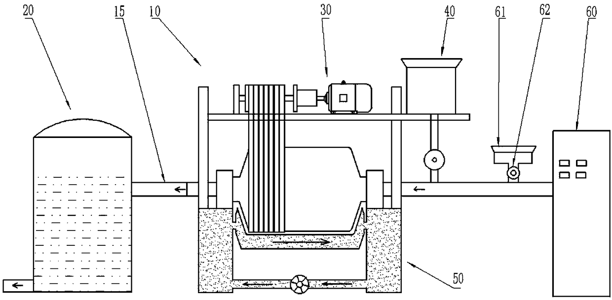
[0037] Such as figure 1 and figure 2 As shown, a slurry grinding delivery system includes a wet ball mill 10, a slurry storage tank 20 and an air compressor 60, and the air compressor 60 transports the waste ground in the wet ball mill 10 to the slurry storage tank 20 via a pipeline 15 Inside, the wet ball mill 10 includes a cylinder 11, a bearing that carries the cylinder 11 and maintains its rotation. The bearings are arranged in the bearing housings 12 at both ends of the bracket 16. The cylinder 11 is driven to rotate through the driving device 30. The upper side of the cylinder 11 A water supply device 40 is provided; a feed port 13 is also included, and the feed port 13 is arranged at one end of the cylinder body 11, and the other end of the cylinder body 11 is provided with a discharge port 14, and the slurry storage tank 20 communicates with the discharge port 14 via a pipeline 15, The output end of the water supply device 40 communicates with the feed material 13 , ...
Embodiment 2
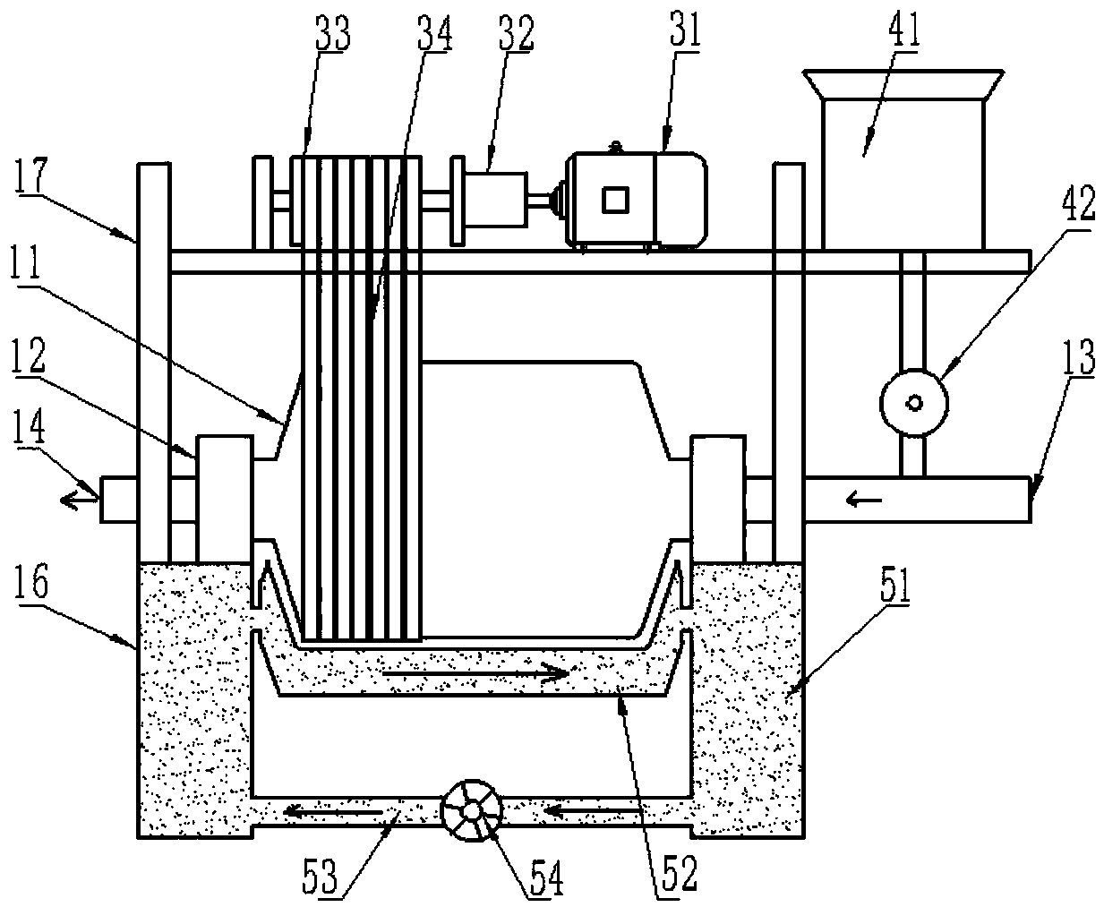
[0041] As shown in Figure 2, the structure of this embodiment is basically the same as that of Embodiment 1, and the similarities will not be repeated. The difference is that a cooling device 50 is provided at the lower end of the cylinder body 11, and the cooling device 50 includes a cooling liquid storage tank. 51, the cooling liquid storage tank 51 is set in the bracket 16, the lower end of the cylinder body 11 is provided with a cooling layer 52 that is adapted to the lower end surface of the cylinder body 11 and the gap is arranged on the lower end surface of the cylinder body 11, and the two ends of the cooling layer 52 are respectively connected with the cooling liquid The storage tank 51 is connected, and the lower end of the cooling liquid storage tank 51 is connected through a circulation pipe 53. The circulation pump 54 is also provided on the circulation pipe 53, and the cooling liquid storage tank 51 is filled with cooling liquid. In this way, in this application, t...
Embodiment 3
[0043] Such as figure 2 As shown, the structure of this embodiment is basically the same as that of Embodiment 1, and the similarities will not be repeated. The difference is that the belt transmission device includes a pulley 33 and a belt 34 that is sleeved on the pulley 33 and the cylinder body 11, and the pulley 33 It is coaxially fixedly connected with the power output shaft of the speed reducer 32, so, in the present application, the belt transmission device includes a pulley 33 and a belt 34 sleeved on the pulley 33 and the cylinder 11, and the power output of the pulley 33 and the speed reducer 32 The shafts are coaxially fixedly connected. Due to the pulling force of the belt 34, the load bearing capacity of the bearings at both ends of the cylinder 11 can be greatly reduced, thereby greatly reducing the friction force of the bearings, thereby reducing the heat generated by the friction of the bearings, and reducing the load of the servo motor. energy consumption.
PUM
 Abstract
Description
Claims
Application Information
 - R&D
- Intellectual Property
- Life Sciences
- Materials
- Tech Scout
- Unparalleled Data Quality
- Higher Quality Content
- 60% Fewer Hallucinations
Browse by: Latest US Patents, China's latest patents, Technical Efficacy Thesaurus, Application Domain, Technology Topic, Popular Technical Reports.
© 2025 PatSnap. All rights reserved.Legal|Privacy policy|Modern Slavery Act Transparency Statement|Sitemap|About US| Contact US: help@patsnap.com