


Quick Research
Generate reliable direction feasibility study reports for your R&D in just a few steps.

Technical Q&A
Discover and master advanced knowledge NOW. Basics, ideas, possibilities, all at once.

Find Solutions
As an expert in R&D theories, this can generate solutions to your technical problems instantly.

Evaluate Feasibility
Analyze your overall solution with one click, know your potential R&D risks in advance.

Monitor Landscape
Get weekly tech updates, stay abreast of the latest tech innovations and key insights.
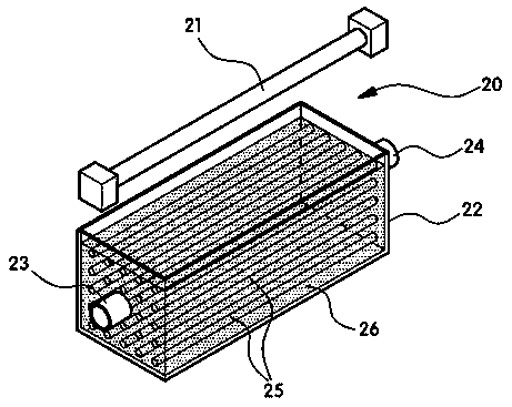
Plasma processing device of gaseous waste
A treatment device and gaseous waste technology, applied in the direction of plasma, electrical components, etc., can solve the problems of difficult pollutant treatment, short reaction time, and limited reaction area
- Summary
- Abstract
- Description
- Claims
- Application Information
AI Technical Summary
Problems solved by technology
Method used
Image

Examples
no. 1 example
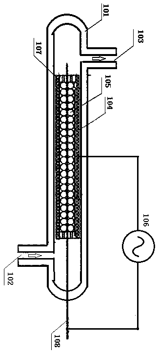
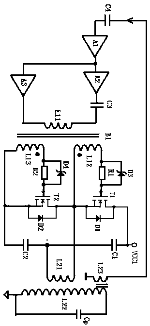
[0030] image 3 It is the composition circuit diagram of the high voltage source provided by the first embodiment of the present invention, such as image 3As shown, the high voltage source includes a boost coil and an active resonator, and the secondary coil 122 of the boost coil forms a resonant circuit with the discharge capacitor Cp; the active resonator includes at least a secondary coil coupled with the boost coil Coil L21, the active resonator resonates to cause the resonant tank to resonate so as to ionize the gas charged into the container to form a plasma, said plasma including at least free radicals.
[0031] The active resonator includes a feedback loop, an amplifier A1, a first drive circuit A2, a second drive circuit A3, a gate drive transformer B1, a first N-channel field effect transistor T1, a second N-channel field effect transistor T2, and a first capacitor C1 And the second capacitor C2, the gate drive transformer B1 includes a primary coil L11 and two sec...
no. 2 example
[0033] Figure 4 It is the composition circuit diagram of the high voltage source provided by the second embodiment of the present invention, such as Figure 4 As shown, the difference between the high voltage source provided by the second embodiment of the present invention and the high voltage source provided by the first embodiment is only the feedback loop, the feedback loop in the second embodiment includes a transformer B3, and the coil L21 is provided with a center tap , the tap is connected to one end of the primary coil L31 of the transformer B3, and the other end of the coil L31 is connected to the output end of the bridge conversion circuit, that is, the source of the first N-channel field effect transistor T1. One end of the secondary coil L32 of the transformer B3 is connected to the amplifier through the variable resistor RW and the capacitor C4, and the other end is connected to the ground. The two ends of the secondary coil L32 of the transformer B3 are connect...
no. 3 example
[0036] Figure 5 It is the composition circuit diagram of the high voltage source provided by the third embodiment of the present invention, such as Figure 5 As shown, the only difference between the third embodiment of the invention and the second embodiment is the primary resonant circuit. In the third embodiment, a capacitor C5 is connected in series with the coil L21 of the primary circuit of the active resonator, and the drive circuit outputs the frequency Equal to the natural frequency of the primary LC equal to the natural frequency of the discharge circuit LC, so that the primary part is in a resonant state, its load characteristics are purely resistive, the power factor is high, and the energy utilization rate is improved. At the same time, because the primary part is resonant, the primary The current rises faster and the instantaneous current is larger. In the third embodiment, the first end of the capacitor C5 is connected to the source of the first N-channel FET,...
PUM
 Abstract
Description
Claims
Application Information
 - R&D Engineer
- R&D Manager
- IP Professional
- Industry Leading Data Capabilities
- Powerful AI technology
- Patent DNA Extraction
Browse by: Latest US Patents, China's latest patents, Technical Efficacy Thesaurus, Application Domain, Technology Topic, Popular Technical Reports.
© 2024 PatSnap. All rights reserved.Legal|Privacy policy|Modern Slavery Act Transparency Statement|Sitemap|About US| Contact US: help@patsnap.com