Electromagnetic upward throwing microgravity device, control method and system
A technology of microgravity and electromagnetic braking, which is applied to the simulation device of spaceflight conditions, transportation and packaging, spaceflight equipment, etc., can solve the problems of low utilization rate of stroke efficiency, short time of microgravity, and high requirements of conveyor belts, etc., to achieve Improve efficiency and realize the effect of full control
- Summary
- Abstract
- Description
- Claims
- Application Information
AI Technical Summary
Problems solved by technology
Method used
Image
Examples
no. 1 example
[0038] see figure 1 , figure 1 It is a schematic structural diagram of an electromagnetic upthrowing microgravity device provided by an embodiment of the present invention.
[0039] Such as figure 1 As shown, the device includes: an electromagnetic transmitter, a speed sensor and a controller, wherein,
[0040] The speed sensor is used for: monitoring the speed of the electromagnetic transmitter to obtain the running speed, and transmit the running speed to the controller, wherein the running speed includes a first running speed and a second running speed.
[0041] During the operation of the electromagnetic upward throwing microgravity device, the operating speed of the electromagnetic launcher is monitored by a speed sensor. It will be appreciated that the electromagnetic launcher is in motion such that the electromagnetic launcher and payload bay handle different phases or modes. Such as: static mode before launch, launch mode during launch, and free-fall movement mode ...
no. 2 example
[0059] This embodiment is based on the first embodiment.
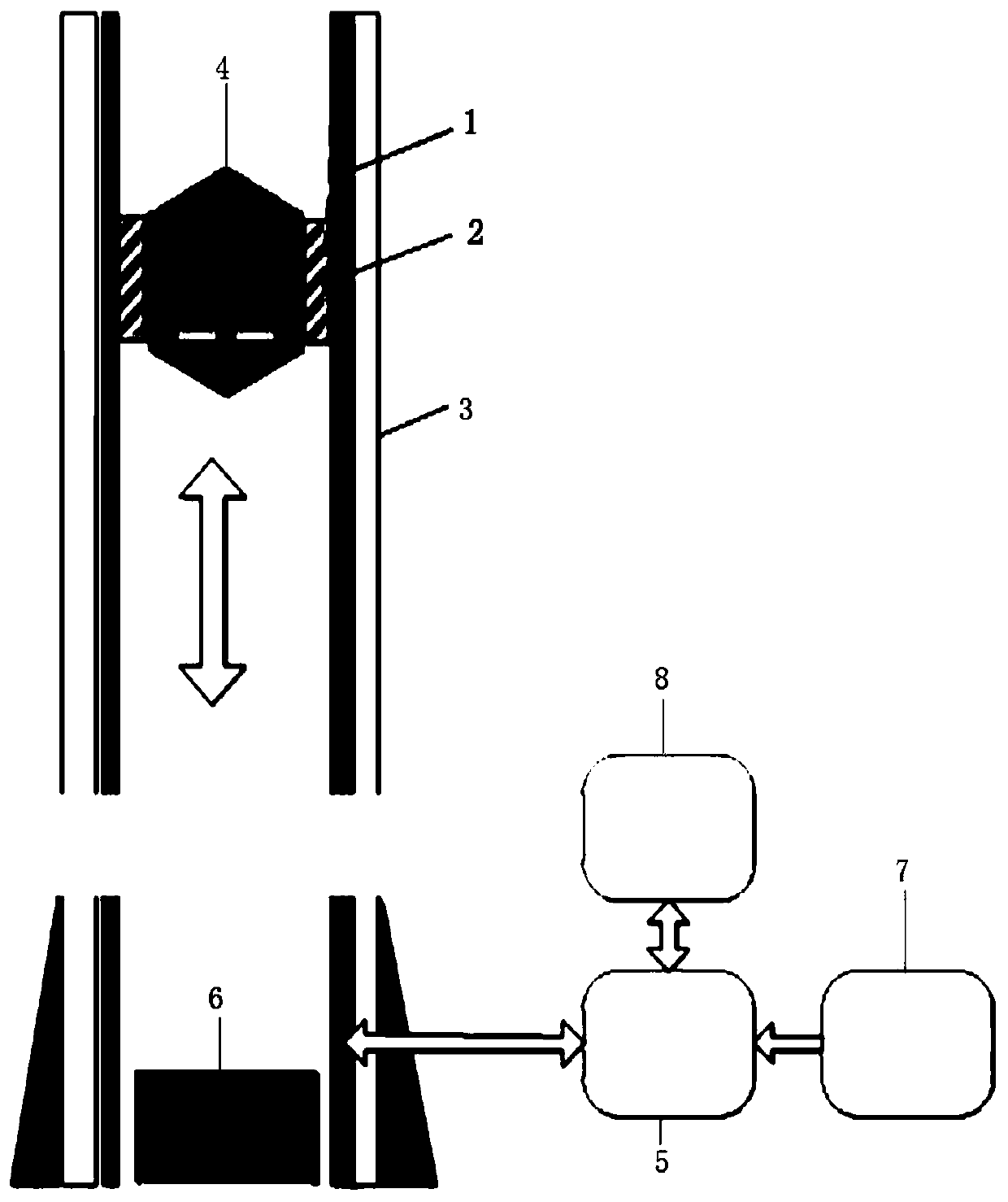
[0060] see figure 2 , figure 2 It is a schematic structural diagram of an electromagnetic upthrowing microgravity system provided by an embodiment of the present invention.
[0061] combine figure 1 and figure 2 , the device also includes: guide rail 3, the electromagnetic launcher includes: mover 2 and stator 1, wherein,
[0062] The guide rail 3 is used for: fixing the stator 1 so that the stator 1 is fixedly installed on the guide rail 3 .
[0063] The speed sensor is specifically used for: monitoring the speed of the mover 2 .
[0064] The speed sensor specifically monitors the speed of the mover 2 in the electromagnetic launcher, so as to obtain the running speed.
[0065] The controller is specifically used for: controlling the mover 2 to carry the payload cabin 4 to launch.
[0066] When the controller controls the electromagnetic launcher to carry the payload capsule 4 to launch, it specifically contr...
no. 3 example
[0071] This embodiment is based on the second embodiment. read on figure 2 .
[0072] The device also includes: a position sensor and a switch 5, wherein,
[0073] The position sensor is used for: monitoring the position of the mover 2, and sending the monitored position information to the controller.
[0074] Since the movement of the electromagnetic transmitter is the movement of the mover, the position of the mover 2 will change. The position of the mover 2 is monitored by using a position sensor.
[0075] When the mover 2 is on the first section of the guide rail, and the controller determines according to the received position information that the distance between the mover 2 and the second section of the guide rail is less than or equal to the preset distance threshold, the controller is used to: turn on the switch 5, In order to supply power to the electromagnetic transmitter through the toggle switch 5 .
[0076] Wherein, the first section of the guide rail and t...
PUM
 Abstract
Description
Claims
Application Information
 - R&D
- Intellectual Property
- Life Sciences
- Materials
- Tech Scout
- Unparalleled Data Quality
- Higher Quality Content
- 60% Fewer Hallucinations
Browse by: Latest US Patents, China's latest patents, Technical Efficacy Thesaurus, Application Domain, Technology Topic, Popular Technical Reports.
© 2025 PatSnap. All rights reserved.Legal|Privacy policy|Modern Slavery Act Transparency Statement|Sitemap|About US| Contact US: help@patsnap.com


