Locating element for accurately machining plunger helix

A plunger screw and positioning element technology, which is applied in the direction of grinding workpiece supports, metal processing equipment, manufacturing tools, etc., can solve the problems of uneven axial force, inconsistent cutting removal amount, low production efficiency, etc., and achieve geometric Improvement of accuracy, consistency of high quality, and reduction of processing dispersion

Active Publication Date: 2018-11-02
STATE RUN NO 616 FACTORY
View PDF8 Cites 0 Cited by
  • Summary
  • Abstract
  • Description
  • Claims
  • Application Information

AI Technical Summary

Problems solved by technology

Two factors can cause a gap between the pressing surface of the positioning plate and the top of the plunger
On the one hand, the appearance of the gap causes the pre-processing distance of the coordinate grinding head of the grinding machine relative to the edge of the plunger spiral groove to be not fixed, the overhang of the workpiece is inconsistent, the size of 8.37±0.045 is seriously out of tolerance, and the reject rate reaches 60%. The axial force is uneven, the amount of cutting removal is inconsistent, and the measured surface roughness is Ra1.25, which cannot meet the technical requirements of the part
[0008] 2. The positioning is cumbersome and the production efficiency is low: During the production process, every time the operator clamps the plunger, he must loosen the hexagonal flange bolt with part number 02 and the hexagonal thin nut with part number 03, and clamp the plunger flange flat and After the outer circle, lock the positioning block under the requirements of ensuring the angle α and the distance H
This positioning method is time-consuming and laborious, and the production efficiency is low.

Method used


Image

  • Locating element for accurately machining plunger helix
  • Locating element for accurately machining plunger helix
  • Locating element for accurately machining plunger helix

Examples


Embodiment Construction

[0033] In order to make the purpose, content and advantages of the present invention clearer, the specific implementation manners of the present invention will be further described in detail below in conjunction with the accompanying drawings and embodiments.

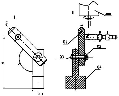
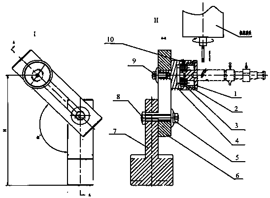
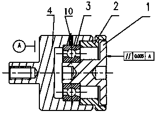
[0034] refer to Figure 3 to Figure 8 As shown, the positioning element of this embodiment is an assembled and combined structure, including: a workbench base 7, a frame plate 6 and a positioning unit, the frame plate 6 is vertically installed on the workbench base 7, and the positioning unit is vertically installed on the frame plate 6 Above, the positioning unit is provided with a positioning block 1. When working, the end face of the positioning block 1 presses against the end face of the top of the plunger to perform axial positioning.

[0035] Wherein, the workbench base 7 and the frame plate 6 are connected and locked by the nut 8 and the first bolt 5 ; the frame plate 6 and the positioning unit are connected and ...


PUM


Abstract

The invention discloses a locating element for accurately machining a plunger helix. The locating element for accurately machining the plunger helix comprises a workbench base, a frame plate and a locating unit. The frame plate is vertically installed on the workbench base. The locating unit is perpendicularly installed on the frame plate. A locating block is arranged on the locating unit. When inwork, the end face of the top of a plunger is tightly pressed by the locating block, and the locating block plays a role in axial location. According to the locating element for accurately machiningthe plunger helix, a selected material is high in abrasion resistance, installation is easy to carry out, the difficulty of making is low, and the requirement for consistency of products is met because bearings are selected as intermediate connecting pieces; adverse factors causing high machining scattering difference of the plunger helix are removed, a preset machining value is achieved, the machining scattering difference of the plunger helix is narrowed, the related geometric accuracy of a plunger and barrel assembly helix is improved, the yield reaches 99%, and consistency of fuel injection of a fuel injection pump assembly is achieved with low cost and high quality.

Description

technical field [0001] The invention belongs to the technical field of machining, and relates to a positioning element used for precisely machining a spiral groove of a plunger. Background technique [0002] The plunger coupling is one of the most important precision couplings in the diesel fuel injection system, consisting of a plunger and a plunger sleeve. Its working principle is the reciprocating movement of the plunger in the plunger sleeve to complete the process of oil suction and pumping of the fuel injection pump; the basic functions are: pressurizing fuel, controlling fuel supply time and fuel supply metering. Its technical indicators and precision indicators have high requirements, and the product structure is special. The product quality has a great influence on the fuel supply uniformity of the fuel injection system, the allowable injection pressure at the pump end, the reliability of the system, and the working process and performance indicators of the diesel e...

Claims


Application Information

Patent Timeline
Patent Type & Authority Applications(China)
IPC IPC(8): B24B41/06B24B19/02
CPCB24B19/022B24B41/061
Inventor 吴建华郭巨寿张波叶榄张鑫
Owner STATE RUN NO 616 FACTORY
Why Eureka
Try Eureka