
Stamping resistance welding welding system and its welding method

A welding system and resistance welding technology, applied in resistance welding equipment, welding equipment, metal processing equipment, etc., can solve the problems of low welding pressure and welding energy, and difficult control of welding and paint removal.

Active Publication Date: 2021-08-13
CHANGZHOU MINGSEAL ROBOT TECH CO LTD
View PDF7 Cites 0 Cited by
  • Summary
  • Abstract
  • Description
  • Claims
  • Application Information

AI Technical Summary

Problems solved by technology

[0003] At present, the wire diameter and pad size of the enameled wire on the market are gradually reduced, and the tin plating thickness of the pad is also gradually reduced or even no longer tinned. At this time, the required welding pressure and welding energy are smaller than the traditional process, and Requires more precise control, making the paint stripping part of welding more difficult to control

Method used


Image

  • Stamping resistance welding welding system and its welding method
  • Stamping resistance welding welding system and its welding method
  • Stamping resistance welding welding system and its welding method

Examples


Embodiment Construction

[0030] Embodiments of the present invention are described in detail below, examples of which are shown in the drawings, wherein the same or similar reference numerals designate the same or similar elements or elements having the same or similar functions throughout. The embodiments described below by referring to the figures are exemplary only for explaining the present invention and should not be construed as limiting the present invention.

[0031] In describing the present invention, it should be understood that the terms "center", "longitudinal", "transverse", "length", "width", "thickness", "upper", "lower", "front", " Back", "Left", "Right", "Vertical", "Horizontal", "Top", "Bottom", "Inner", "Outer", "Clockwise", "Counterclockwise", "Axial", The orientation or positional relationship indicated by "radial", "circumferential", etc. is based on the orientation or positional relationship shown in the drawings, and is only for the convenience of describing the present invent...


PUM


Abstract

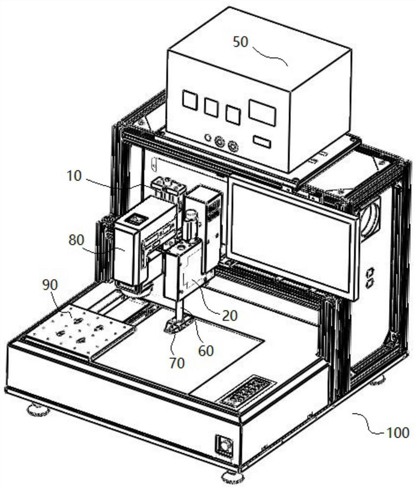
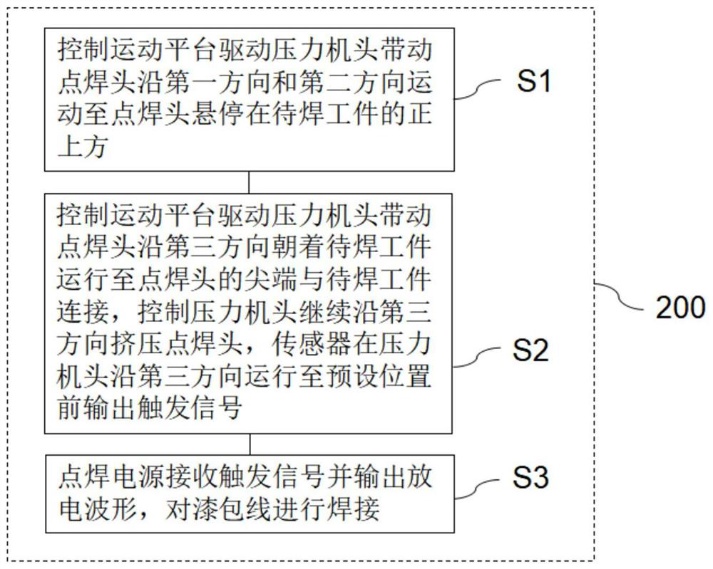
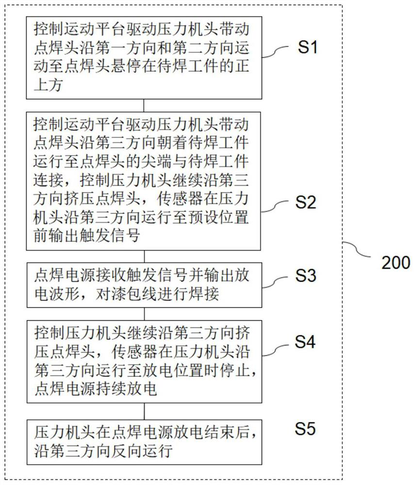
The invention discloses a stamping resistance welding welding system and a welding method thereof. The stamping resistance welding welding system is used for welding workpieces to be welded in microelectronic assembly. The stamping resistance welding welding system includes: a motion platform; direction, the second direction and the third direction are movable, and any two of the first direction, the second direction and the third direction are perpendicular to each other; the spot welding head is set at the end of the press head adjacent to the workpiece to be welded; the sensor is at the When the press head moves to the preset position along the third direction, it outputs a trigger signal; the welding power source can receive the trigger signal and perform discharge, paint removal and welding on the enameled wire. Its welding method receives the sensor sensing signal and outputs the discharge trigger signal before the spot welding head moves to the set welding position, and realizes efficient paint removal and reliable welding by means of punching discharge. This stamping resistance welding welding system is suitable for welding magnet wire with small coils to tinned pads in microelectronics assembly.

Description

technical field [0001] The invention relates to a stamping resistance welding welding system and a welding method of the stamping resistance welding welding system. Background technique [0002] When welding the thin-diameter enameled wire to the pad, it usually includes two processes of paint removal and fusion. The paint removal link is caused by the instantaneous high temperature scalding generated by the milliohm-level internal resistance heating of the tip of the spot welding head and the contact area of ​​the spot welding head. Paint skin, to expose the conductive copper core of the enameled wire, the fusion link is conducted by the tip of the spot welding head and the workpiece to be welded to obtain a lower equivalent resistance value, resulting in higher welding energy to achieve workpiece welding. In the specific welding process, there are a large number of differences in the key parameters of the workpiece to be welded (such as enameled wire diameter, coating thic...

Claims


Application Information

Patent Timeline
Patent Type & Authority Patents(China)
IPC IPC(8): B23K11/02B23K11/36
CPCB23K11/02B23K11/36
Inventor 张晋曲东升赵亚军
Owner CHANGZHOU MINGSEAL ROBOT TECH CO LTD
Learn More