Al technical title is built by PatSnap Al team. It summarizes the technical point description of the patent document.
A composite machine and glue technology, applied in the direction of layered products, lamination devices, lamination, etc., can solve the problems of slow self-adhesive bonding, unreasonable structure setting, no shock absorbing device, etc., and achieve simple structure , reasonable design and convenient operation
Inactive Publication Date: 2018-10-30
江苏庞氏机械有限公司
View PDF0 Cites 1 Cited by
Summary
Abstract
Description
Claims
Application Information
AI Technical Summary
This helps you quickly interpret patents by identifying the three key elements:
Problems solved by technology
Method used
Benefits of technology
Problems solved by technology
At present, a self-adhesive compound machine lacks a mechanism for manually adjusting the tightness of the material, and there are two types of oil-based glue and water-based glue, which cannot be used for the corresponding materials. Because the self-adhesive bonding is slow, so the current A self-adhesive compound machine lacks a heating device to improve production efficiency, and the base of an existing self-adhesive compound machine does not have a shock absorber, the structure is unreasonable, and it is inconvenient to use
Method used
Image
Click on the blue label to locate the original text in one second.
Reading with bidirectional positioning of images and text.
Examples
Embodiment Construction
[0016] The following will clearly and completely describe the technical solutions in the embodiments of the present invention in conjunction with the accompanying drawings in the embodiments of the present invention. Obviously, the described embodiments are only a part of the embodiments of the present invention, rather than all the embodiments. The embodiments of the present invention and all other embodiments obtained by those of ordinary skill in the art without creative work shall fall within the protection scope of the present invention.
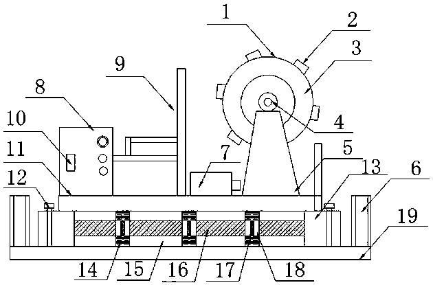
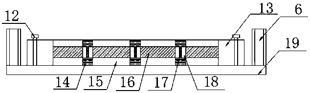
[0017] Such as Figure 1-2 As shown, the present invention provides a self-adhesive laminating machine, including a laminating machine body 1, a support base 2, a heat roller 3, a rotating shaft wheel 4, a support base 5, a baffle 6, a drive motor 7, a glue tank 8, and a support rod 9. Glue injection port 10, support plate 11, bolt 12, shock absorption device 13, shock absorption air plug 14, shock absorption block 15, shock absorption spr...
PUM
Abstract
The invention relates to an adhesive sticker laminating machine which comprises a laminating machine body, support seats, a hot roller, a rotating shaft wheel, a support seat, baffles, a driving motor, a glue case, a support rod, a glue filling port, a support plate, bolts, a shock absorption device, shock absorption air plugs, shock absorption blocks, a shock absorption spring, elastic air cylinders, shock absorption air bags and a base, wherein the support plate is arranged at the bottom end of the laminating machine body; the support seat is arranged on the support plate; the hot roller isfixedly mounted on the support seat; the rotating shaft wheel is arranged in the hot roller; the driving motor is mounted on one side of the support seat; the support rod is mounted on one side of thedriving motor and connected with the glue case; the glue filling part is formed in the glue case; the shock absorption device is arranged at the bottom of the support plate; the tops of the two sidesof the shock absorption device are fixedly mounted and matched by the bolts, so that the laminating machine body is fixedly connected with the base; and the laminating machine has a dismountable function, and is simple in structure, reasonable in design, convenient to operate, low in cost and easy to popularize and use.
Description
Technical field [0001] The invention relates to the field of composite machine equipment, in particular to a self-adhesive composite machine. Background technique [0002] Self-adhesive, also called self-adhesive label material, is a composite material with paper, film or special material as the fabric, adhesive coated on the back, and silicon-coated protective paper as the base paper. Due to the various coating technologies, the self-adhesive materials are formed in different grades. The current development direction is to develop from the traditional roll coating and knife coating to the high-pressure cast coating direction to ensure maximum coating quality. Uniform sensitivity, avoid the generation of bubbles and pinholes, and ensure the coating quality. However, the domestic technology of cast cloth coating is not mature, and the traditional roller coating is mainly used in China. The laminating machine is to bond two or more materials together with an adhesive. Such as fil...
Claims
Application Information
Patent Timeline
Application Date:The date an application was filed.
Publication Date:The date a patent or application was officially published.
First Publication Date:The earliest publication date of a patent with the same application number.
Issue Date:Publication date of the patent grant document.
PCT Entry Date:The Entry date of PCT National Phase.
Estimated Expiry Date:The statutory expiry date of a patent right according to the Patent Law, and it is the longest term of protection that the patent right can achieve without the termination of the patent right due to other reasons(Term extension factor has been taken into account ).
Invalid Date:Actual expiry date is based on effective date or publication date of legal transaction data of invalid patent.