
Automatic steel pipe feeding device

A technology of automatic feeding and steel pipes, applied in the direction of transportation and packaging, conveyor objects, etc., can solve the problems of long length, low work efficiency, hidden safety hazards, etc.

Inactive Publication Date: 2018-10-26
山东三维重工有限公司
View PDF0 Cites 6 Cited by
  • Summary
  • Abstract
  • Description
  • Claims
  • Application Information

AI Technical Summary

Problems solved by technology

[0002] In today's society, steel pipes are widely used, and now more and more are used in the field of photovoltaic solar energy. In the process of drilling steel pipes, it is necessary to put steel pipes of fixed size on the steel pipe drilling line. It is relatively heavy, and the length is relatively long. In the past, the bundled steel pipes were placed on the feeding rack with a slope, and the steel pipes were manually transferred to the conveyor of the drilling machine one by one. The personnel frequently reciprocated work, which increased It reduces the labor intensity of the operator, and sometimes it is easy to squeeze together with the pipes and enter the conveyor, and the work efficiency is also very low
Due to the high labor intensity and long working hours, there are great potential safety hazards, and small abrasion accidents often occur

Method used


Image

  • Automatic steel pipe feeding device
  • Automatic steel pipe feeding device
  • Automatic steel pipe feeding device

Examples


Embodiment Construction

[0026] Provide specific implementation method of the present invention below in conjunction with accompanying drawing:

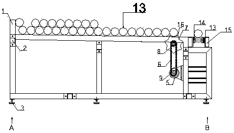
[0027] As shown in the figure, it includes a material storage system, a material transfer system, and a material delivery system. The material storage system stores and places steel pipes. The height of the storage rack 1 gradually decreases from the starting end A to the end B end. 1. Rolling from the starting end A to the end B under the action of gravity; the feeding system is connected to the end of the storage system, and the steel pipe 13 is transported to the processing device by the feeding system. The automatic feeding system of the present invention utilizes a distance sensor, which is an infrared sensor that can feel the distance between E and F, and the position of the distance sensor 11 is fixed, no matter which one the distance sensor 11 is in at the beginning. position, when an initial start signal is given to the motor 5, the dial shaft 12 dr...


PUM


Abstract

The invention relates to an automatic steel pipe feeding device. The automatic steel pipe feeding device can realize the automatic transportation of steel pipes without manpower to carry and shift steel pipes. The automatic steel pipe shifting and transportation are realized by an inductor. The steel pipes are stored and placed in a material storage system, the height, from the beginning to the end, of the material storage system gradually decreases, and the steel pipes can roll along the material storage system from the beginning to the end under the action of gravity. A material shifting system is connected to the tail end of the material storage system and shifts the steel pipes sliding to the tail end of the material storage system to a material conveying system, and the steel pipes are transported to a processing device by the material conveying system. Rotating shifting discs are arranged on the material shifting system, and the steel pipes are shifted to the material conveying system by rotating the shifting discs. A distance sensor is arranged on the material shifting system, and distance sensor stop dogs are arranged on the shifting discs. When the steel pipes on the material conveying system leave the material conveying system, the material shifting system is started, and the shifting discs rotate to shift the next steel pipes to the material conveying system; and meanwhile, the distance sensor stop dogs on the shifting discs block a sensor, the distance sensor feeds back a signal to the material shifting system, and the material shifting system stops shifting.

Description

technical field [0001] The invention belongs to the technical field of steel pipe transportation, in particular to an automatic feeding device for steel pipes. Background technique [0002] In today's society, steel pipes are widely used, and now more and more are used in the field of photovoltaic solar energy. In the process of drilling steel pipes, it is necessary to put steel pipes of fixed size on the steel pipe drilling line. It is relatively heavy, and the length is relatively long. In the past, the bundled steel pipes were placed on the feeding rack with a slope, and the steel pipes were manually transferred to the conveyor of the drilling machine one by one. The personnel frequently reciprocated work, which increased It reduces the labor intensity of the operator, and sometimes it is easy to squeeze more pipes into the conveyor, and the work efficiency is also very low. Because of the high labor intensity and long working hours, there are great potential safety haza...

Claims


Application Information

Patent Timeline
IPC IPC(8): B65G47/84
CPCB65G47/846
Inventor 杨维生张厚祥杨硕邱玉国孔凡虎唐辉陈娅娅张冉
Owner 山东三维重工有限公司
Learn More