
Zero-phase startup circuit

A start-up circuit and zero-phase technology, applied in the field of power supply, can solve the problems of no protection, inability to effectively protect the power supply, potential safety hazards, etc., and achieve the effect of simple and reliable circuit, superior EMC performance and low cost

Pending Publication Date: 2018-10-23
MORNSUN GUANGZHOU SCI & TECH
View PDF5 Cites 1 Cited by
  • Summary
  • Abstract
  • Description
  • Claims
  • Application Information

AI Technical Summary

Problems solved by technology

Among them, the method of increasing the upper limit of the input voltage of the power supply is mainly to use high withstand voltage devices or multi-stage series-parallel methods. And the volume increases, and when the power supply is started at +90° or -270° high phase voltage, the high voltage current will break down the switching device MOS tube in the power module and cause the power supply to explode, which cannot effectively protect the power supply
[0004] In the three-phase four-wire power meter and feeder grid automation industry, the switching power supply on the market today does not provide protection against the above problems. When the power supply starts with a high phase voltage of +90° and -270°, the electrolytic capacitor and the switching tube are often used. Exceeding the standard hard resistance, there is a huge potential safety hazard

Method used


Image

  • Zero-phase startup circuit
  • Zero-phase startup circuit
  • Zero-phase startup circuit

Examples


no. 1 example

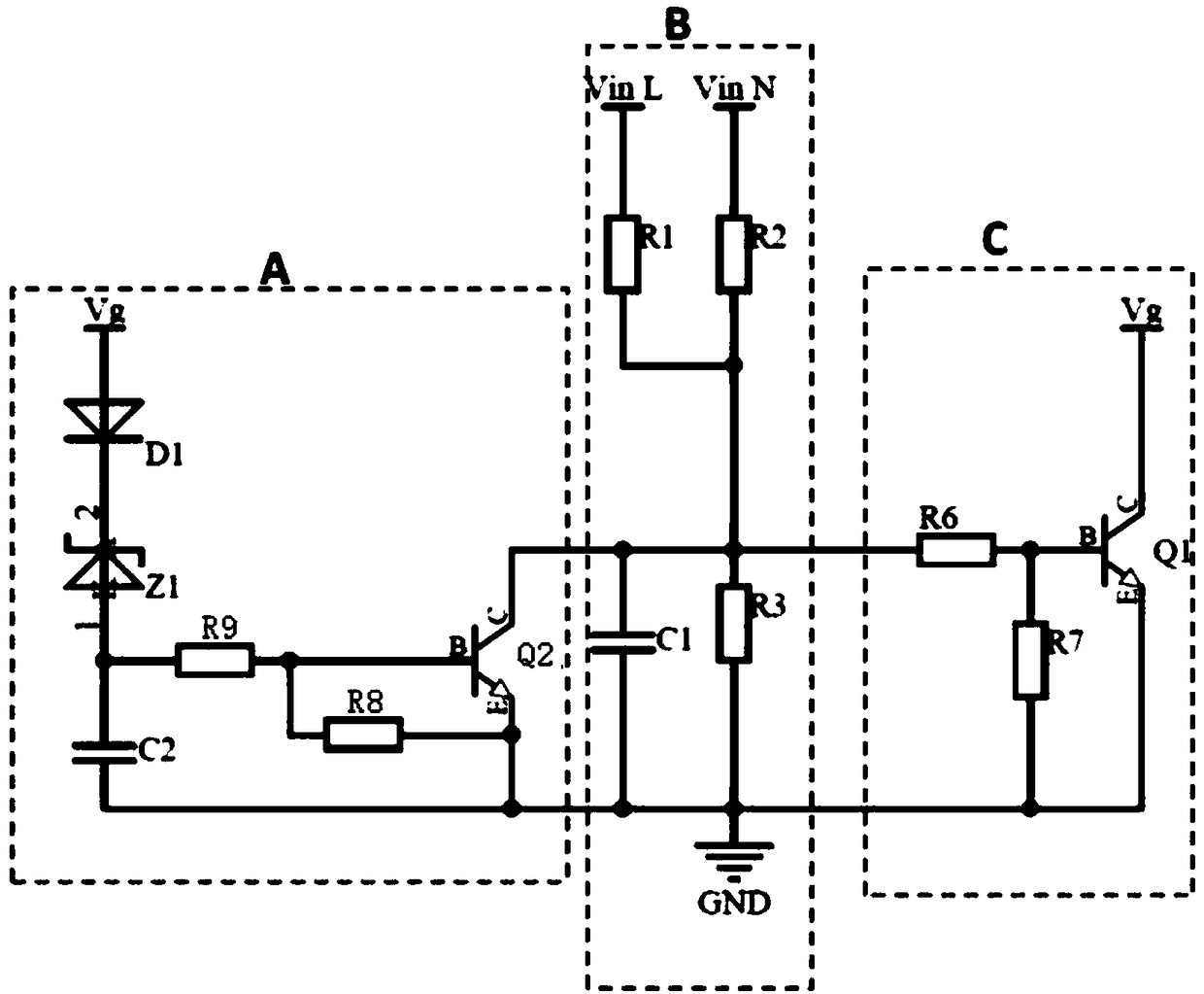
[0030] figure 2 It is the schematic diagram of the zero-phase starting circuit of the first embodiment of the present invention, as shown in the figure:

[0031] Input sampling circuit, including: resistor R1, resistor R2, resistor R3, capacitor C1; the connection relationship is:

[0032] One end of the resistor R1 is connected to the positive input terminal VinL, the other end of the resistor R1 is connected to one end of the resistor R3, one end of the resistor R2 is connected to the negative input terminal VinN, the other end of the resistor R2 is connected to one end of the resistor R3, and the connection node between the resistor R1 and the resistor R2 is used as Input the output terminal of the sampling circuit, the other end of the resistor R3 is connected to the ground; the capacitor C1 is connected in parallel to both ends of the resistor R3, wherein the capacitor C1 is a filter capacitor.

[0033] The control circuit includes: resistor R6, resistor R7, and transis...

no. 2 example

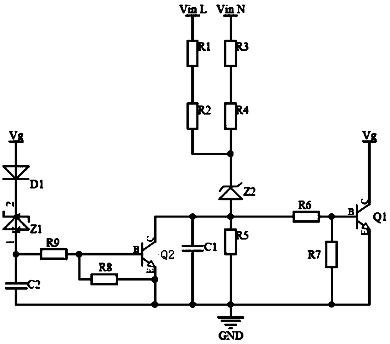
[0039] image 3 It is the schematic diagram of the zero-phase starting circuit of the second embodiment of the present invention. The difference from the first embodiment is that the input sampling circuit includes: resistor R1, resistor R2, resistor R3, resistor R4, resistor R5, regulator tube Z2, capacitor C1; one end of the resistor R2 is connected to the positive input terminal of the zero-phase starting circuit through the resistor R1, and the other end of the resistor R2 is connected to the cathode of the voltage regulator tube Z2, and the cathode of the voltage regulator tube Z2 is also connected to the zero phase through the resistor R4 and the resistor R3 in turn. The input terminal of the phase starting circuit is negative, the anode of the voltage regulator tube Z2 is used as the output terminal of the input sampling circuit, the anode of the voltage regulator tube Z2 is also connected to the ground through the resistor R5, and the capacitor C1 is connected in parall...

no. 3 example

[0042] Figure 4 It is the schematic diagram of the zero-phase start-up circuit of the third embodiment of the present invention. The difference from the first embodiment is that

[0043] The input sampling circuit includes: resistor R1, resistor R2, resistor R3, resistor R4, resistor R5, capacitor C1, and voltage regulator tube Z2; one end of resistor R1 is positively connected to the input end of the zero-phase starting circuit, and the other end of resistor R1 passes through the resistor R2 and capacitor C1 are connected to the ground, one end of the resistor R3 is negatively connected to the input terminal of the zero-phase start circuit, the other end of the resistor R3 is connected to the ground through the resistor R4 and the resistor R5 in turn, the connection point of the resistor R2 and C1, the resistor R4 and the resistor R5 This node is used as the output terminal of the input sampling circuit, the cathode of the Zener tube is connected to one end of the resistor R...


PUM


Abstract

The invention discloses a zero-phase startup circuit, which comprises an input positive end, an input negative end, an output end, an input sampling circuit, an anti-jitter circuit and a control circuit, wherein the input end of the input sampling circuit is connected with the input positive end and the output negative end of a zero-phase circuit; the output end of the input sampling circuit is connected with the input end of the control circuit and the output end of the anti-jitter circuit; the output end of the control circuit is the output end of the zero-phase startup circuit; the input end of the anti-jitter circuit is connected with the output end of the zero-phase startup circuit; and the output end of the zero-phase startup circuit is connected with a switch control device of an external post-stage circuit. the zero-phase startup circuit is applicable to all input AC power supplies, in particular, power products applied to a power grid environment, the circuit is simple and reliable, the cost is low, the EMC performance is excellent, the design is flexible, and a protection threshold can be adjusted.

Description

technical field [0001] The invention relates to the field of power supplies, in particular to a zero-phase starting circuit used in automatic power supply systems of three-phase four-wire and feeder grids. Background technique [0002] In the switching power supply of the three-phase four-wire power meter and the feeder automation industry, the power supply will be frequently started and shut down. When the high-voltage phase starts, the voltage and current of the grid will exceed the upper voltage limit that the switching power supply can withstand, which will easily cause damage to the switching power supply or even cause a fire, posing a huge safety hazard; [0003] There are mainly two methods for the existing switching power supply to solve the problem of high grid voltage. One is to increase the input overvoltage protection circuit, and the other is to increase the upper limit of the operating voltage range that the power supply can withstand. Among them, the method o...

Claims


Application Information

Patent Timeline
Patent Type & Authority Applications(China)
IPC IPC(8): H02M1/36
CPCH02M1/36H02M1/0058Y02B70/10
Inventor 罗皓卢六里程志勇
Owner MORNSUN GUANGZHOU SCI & TECH
Learn More