Tactile feedback exoskeleton device based on vibration and pneumatic combination

A technology of tactile feedback and exoskeleton, which is applied in the direction of manipulators, program-controlled manipulators, manufacturing tools, etc., can solve the problems of no tactile feedback, no simulated tactile experience, etc., and achieve the effect of easy portability, real touch and portability

Pending Publication Date: 2018-10-23
金子楗
View PDF13 Cites 1 Cited by
  • Summary
  • Abstract
  • Description
  • Claims
  • Application Information

AI Technical Summary

Problems solved by technology

[0006] The purpose of the present invention is to solve the problem that the exis...

Method used


Image

  • Tactile feedback exoskeleton device based on vibration and pneumatic combination
  • Tactile feedback exoskeleton device based on vibration and pneumatic combination
  • Tactile feedback exoskeleton device based on vibration and pneumatic combination

Examples


Embodiment 1

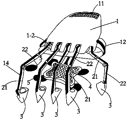
[0032] In order to solve the problem of no tactile feedback and no simulated tactile experience in existing VR technical equipment, this embodiment provides a method such as figure 1 The shown tactile feedback exoskeleton device based on the combination of vibration and pneumatics includes a simulated palm 1 set on the back of the human hand, five simulated fingers 2 set on the five fingers of the human body, and five simulated fingers 2 are set on the simulated palm 1 for fixing the rudder. The card slot of the steering gear 1-2, and the roots of the five simulated fingers 2 are respectively connected to the steering gear 1-2 through the transmission shaft;

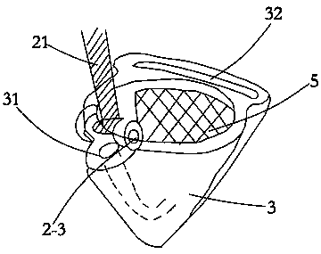
[0033] The simulated finger 2 of the present embodiment has 15 degrees of freedom, wherein: the knuckles of the five simulated fingers 2 have one degree of freedom respectively, and the fingertips of the five simulated fingers 2 are respectively movably connected with a fingertip 3, the fingertip 3 is set on the fingers ...

Embodiment 2

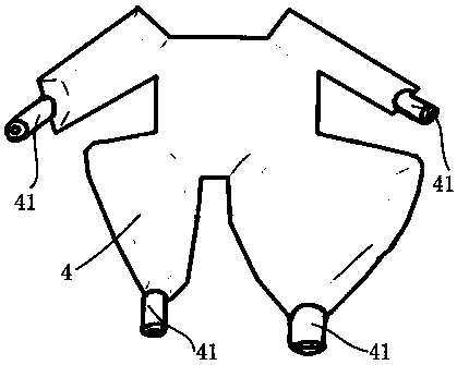
[0052] The difference from the above embodiment is that the simulated finger 2 of this embodiment has 16 degrees of freedom. Among them, the thumb, index finger, middle finger, ring finger, and little finger of the simulated finger 2 each have a degree of freedom, and the metacarpal bone has a degree of freedom.

[0053] Wherein, the thumb, forefinger, middle finger, ring finger, and little finger can be made up of fingertip section 21, middle section and finger root section 22 respectively, and one end of fingertip section 21 is connected flexibly with finger cot 3, and the other end of fingertip section 21 is connected with the middle section. One end of the section is fixedly connected, and the other end of the middle section is movably connected with one end of the root section 22, and the other end of the root section 22 is movably connected with the steering gear 1-2 through a transmission shaft, so that the fingers have five degrees of freedom.

[0054] The simulated fi...


PUM


Abstract

The invention relates to a tactile feedback exoskeleton device based on vibration and pneumatic combination. The tactile feedback exoskeleton device comprises a simulated palm and five simulated fingers; the finger roots of the five simulated fingers are movably connected with a steering engine through a transmission shaft; one degree of freedom is set at each knuckle of each of the five simulatedfingers, the fingertip of each of the simulated fingers is movably connected with a finger sleeve, and a vibrating sheet is fixedly arranged on each finger sleeve; the simulated palm is provided witha cavity structure, a first gas inlet communicating with the cavity is formed in the simulated palm, a gas jetting opening is formed in each finger sleeve, and a gas guiding pipe is arranged on eachsimulated finger; and one end of each gas guiding pipe communicates with the cavity of the simulated palm, and the other end of each gas guiding pipe communicates with the corresponding gas jetting opening. According to the tactile feedback exoskeleton device, by simulating the fingers to limit the hand movement to display the pressure sensation, a more realistic tactile sensation is provided fora wearer; and meanwhile, by simulating the tactile sense of the human skin by using the gas flow vortex and vibration, the tactile feedback exoskeleton device has the characteristics of being small insize, easy to carry and real in simulation of the tactile sense of the human body.

Description

technical field [0001] The invention belongs to the technical field of VR equipment, and in particular relates to a tactile feedback exoskeleton device based on the combination of vibration and pneumatic. Background technique [0002] Virtual reality technology (Virtual Reality, hereinafter referred to as VR technology) is an important direction of simulation technology and a challenging cross-technology frontier discipline and research field. It records human behavior and actions, and the computer processes the data adapted to the participants' actions, and responds to the user's input in real time, and then feeds back to the user's five sense organs respectively to realize human-computer interaction. [0003] At the same time, with the rapid development of VR technology, augmented reality technology (Augmented Reality, hereinafter referred to as AR technology) is also quietly born. It puts physical information (visual information, sound, taste, touch, etc.) that are diffi...

Claims


Application Information

Patent Timeline
IPC IPC(8): B25J9/00B25J9/16
CPCB25J9/0006B25J9/1633
Inventor 张介憧甘海林晋宇飞金子楗韩翔宇许子琪梅潇然许睿
Owner 金子楗
Why Eureka
Try Eureka